 Review Article
Abstract
Nebulizers process has been utilized for the past forty years with great convenience for materials processing, especially for the fabrication of metal oxide thin films of semiconducting nature. The process renders several advantages associated to the adhesion, control of morphology, particle size, and homogeneity of thin films, apart from its low cost. In this brief review, we present a short description of nebulizers nebulization process of liquid through nebulizers wave induced cavitation. Effects of different parameters like the ultrasound frequency, nebulizers power, and fluid level in the atomization chamber on the nebulization rate of a liquid solvent of precursor have been discussed.
Keywords: Ultrasonic Spray Pyrolysis; Thin Solid Films; Nebulizers Process
Introduction
Powder or film generation by aerosol processes involves a number of steps, or unit operations. For example, powder generation by spray pyrolysis involves atomizing a solution to form droplets, entraining the droplets in a gas stream to form an aerosol, transporting the aerosol to a heat source, heating the droplets to drive the reactions to form the products, collecting the powder, and cleaning up gaseous by-products. Similarly, powder generation by gasto-particle conversion involves delivering gaseous reactants to a heat source (the reactor), inducing the desired chemicals to react, collecting the powder that forms, and cleaning up gases. Film formation requires either the generation and deposition of droplets or the delivery of gaseous materials. In this chapter, we discuss the separate operations that together form an aerosol powder or film generation system. Droplet generators, virtual and conventional impactors, cyclones, volatile precursor delivery systems, and powder collection by electrostatic precipitation and filtration are examined. For background, the reader is referred to Bayvel, et al. [1] and LeFebvre [2] for sprays; to Kodas, et al. [3] for delivery al reactants; and to Willeke, et al. [4] for all other topics.
Atomization
Introduction
The devices used to convert bulk liquids into droplets are usually called atomizers or nebulizers. Atomization is used in a variety of applications involving the generation and processing of fine particles. Liquid metal atomization is widely used to produce metal powders with diameters of 1 to 5000μm [5-7]. Powders obtained by this route are used for the production of sintered machine parts, soldering materials, and metal pastes used to from patterns on circuit boards. Two starting points for information are the texts by Rayvel, et al. [1] and Lefebvre [2]. Atomization is also used to deposit anticorrosion coatings, plastics, resin, adhesives, and ceramic and stoneware glazing. It is utilized to wash and clean parts in Order to prepare them for subsequent physical or chemical processes in the microelectronics industry. Atomization is the basis of spray-drying in which liquids are sprayed into a heated gas stream to remove the moisture. The water or other liquid evaporates quickly because of the large surface area of the drops. Atomization also plays a key role in spray pyrolysis (Figure 1) for powder production. In this case, droplet sizes are usually 0.1 to 100μm, significantly smaller than those used for spray-drying. Various rout to thin solid films so exploit atomization. Droplet deposition relies on the generation of droplets of in volatile reactants. AACVD utilizes droplets of solutions of volatile precursors (Figure 2). The requirements for the droplet size distribution and, therefore, the atomizer, vary, depending on the application and scale, laboratory or industrial. The discussion that follows outlines the differences among atomizers, describes their relevant characteristics, and explains which types of atomizers are suitable for the various aerosol routes to materials.
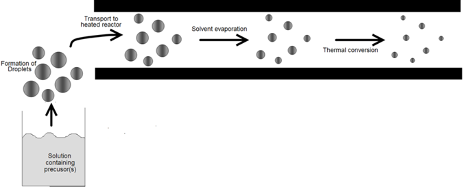
Figure 1: A schematic diagram of influenza A virus.
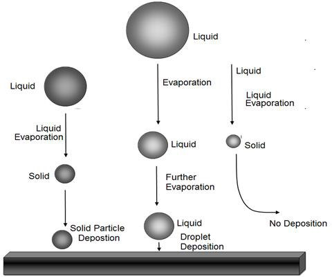
Figure 2: Droplet of different size can behave differently during deposition. Large droplets may deposit as droplets, while smaller may lose all solvent and form solid particles that may or may not deposit.
Classification of Atomizers
Atomizers can be classified by means of various approaches, such as the type of energy used for atomization. The simplest class of atomizers uses the energy of the liquid itself to drive the breakup of the liquid; the pressure of the fluid is converted into kinetic energy, which atomizes the Iiquid. These atomizers can be classified into three types: jet atomizers, swirl atomizers, and jet-swirl atomizers [1,2]. Jet atomizers themselves can be grouped into two types: continuous and intermittent. Continuous atomizers are the simplest of all atomizers, while intermittent atomizers are the most complex. Jet atomizers produce jets that break apart as they leave the atomizer. High injection pressures are required to produce the kinetic energy necessary to break up the fluid into sufficiently small droplets. Swirl atomizers are the most widely used of all types of atomizers because they require lower pressures than jet atomizers.
Swirl atomizers exploit the swirling of a liquid inside an atomizer to give a conical sheet of liquid that break up more easily than a jet. Jet-swirl atomizers combine the features of jet and swirl atomizers. Pneumatic or gas-assist atomizers use the energy of a carrier gas to break up sheets or jets of a liquid. Pneumatic atomizers are the most complex of the atomizers because the liquid and gas phases interact in a complex manner. A common mode of interaction is the transverse introduction of a liquid stream into a high-velocity gas stream. Rotary atomizers impinge a liquid onto a rapidly rotating surface, usually driven by electric motors that transmit its rotational energy to the liquid, causing it to leave the atomizer with high kinetic energy and break apart. This type of atomizer can provide narrow size distributions under the correct operating conditions. Rotary atomizers are often used in the atomization of solutions, because they with a liquid al low pressure. They are common in spray-drying systems. Other types of atomizer, rely on more exotic phenomena to convert the liquid into droplets. Examples are nebulizers and electro spray atomizers. These atomizers have been used extensively al the laboratory scale for aerosol routes to materials because of their ability to produce smaller droplets than can be obtained by other methods. One of the major challenges for atomization technology is the production of high concentrations of droplets with small sizes. Most atomizer technologies e.g., jet, gas-assist, and rotary atomizers-when operated al industrial rates, produce droplets with diameters greater than 10μm and concentrations lower than 107 droplets/cm3. A variety of applications, including especially spray pyrolysis for powder generation, require droplets of 1 to 10μm in size at concentrations greater than 107 droplets/cm3 (but below the coagulation limit of roughly 109 droplets/cm3). This has led to an emphasis on nebulizers, electrostatic, and other technologies capable of producing droplets with sizes less than 10μm at high concentrations. The conventional jet, gas-assist, rotary, etc., atomizer technologic have been discussed in detail in various books [1,2]. For this reason, we focus our discussion un less conventional approaches, including nebulizers and electrostatic atomizers.
Pressure and Two-Fluid Atomization
In general, pressure and two-fluid atomizers cannot easily produce high concentrations of droplets smaller than 1μm. Several designs are available for droplets in the 1 to 10μm range [8], and massive number of atomizers are available for droplets greater than 10μm. We shall concentrate on the discussion of atomizers capable of producing droplets less than 10μm in size. The physical phenomena that are exploited to produce droplets by these routes vary. Pressure atomizers work by discharging a liquid through a small aperture under high pressure. They have the advantage of not requiring any associated gas flow (therefore. high droplet concentrations can be achieved), but have the disadvantage of producing large droplet, sizes. Rotary atomizers work by centrifugal atomization: A liquid is directed onto a rotating element that converts the liquid stream to droplets. These atomizers, too, have the advantage of not requiring any associated gas flows, but have the disadvantage of providing large droplet sizes. Air-assistatomizer expose the liquid to a stream of air flowing al high Velocity. They require a gas flow to produce droplets, but have the advantage of providing somewhat smaller droplet sizes than are produced by pressure and rotary atomizer. Air-blast atomizer are similar to air-assist nozzles, but use much higher quantities of air or stream, these atomizers are discussed by Lefebvre and will not be examined here [2].
Many variation of the Collison (not collision) design of produce droplets whit sizes on the order of 1μm [9,10]. The Collison design relies on drawing a liquid stream in to a high-velocity gas stream that atomizes the liquid. The gas stream makes a sharp bend, and the larger droplets impact on the surface because of their greater inertia, while the smaller particles (with less inertia) follow the gas stream, thereby narrowing the size distribution and reducing the average droplet size. A typical design is shown in Figure 3. This particular atomizer produces droplets less than 1μm in size. Several designs (BGI. TSI) are available that produce droplet concentrations of 106 to 107 /cm3 and sizes of 1 μm or less. Effervescent atomization has been used for spray pyrolysis applications at the laboratory scale. This technique is illustrated in Figure 4 [11]. The fluid to be atomized is pressurized to sufficient levels to dissolve significant quantities of the carrier gas in the liquid. The liquid is atomized into a region at atmospheric pressure in which the dissolved gas comes out of solution, resulting in further breakdown of the droplets. Droplet sizes are usually greater than 1μm, but high throughputs are obtained relative to the Collision design.
Figure 3: Collision-type aerosol generator capable of producing high concentrations of submicron-sized droplet.
Figure 4: Effervescent spray system in which gas is dissolved in the liquid to be atomized and then forms bubble in the gas after exiting the nozzle, thereby breaking up the liquid stream into small droplets [11].
Nebulizers Atomizers
Nebulizers atomizers use an nebulizers transducer or horn that vibrates at nebulizers frequencies (typically, 50kHz-2.4MHz) to produce the short wavelengths required for liquid atomization [12-19] the most useful characteristics of nebulizers atomizers for materials processing by aerosol techniques are their low spray velocity the small or nonexistent amount of carrier gas required to operate them, and the small droplet size produced, which can be less than 10μm. This makes it easy to carry small droplets at a high concentration into a flow reactor or towards a surface without using a high gas flow. Because of these useful characteristics, nebulizers atomizers have been employed extensively in aerosol methods for generating both film and powders at the laboratory and on industrial scales. These types of atomizers are also used to spray acidic or basic solutions onto semiconductor wafers to etch features into them. There are three classes of nebulizers atomizers. One version passes the liquid through a tube that is driven nebulizersally (Figure 5) [20]. In the other version, the liquid comes into contact with an nebulizers horn, or the nebulizers transducer is submerged in the liquid (Figure 6) [21]. The principle of operation is similar for these examples of nebulizer’s atomizers. When a liquid come into contact with the nebulizersally driven surface, a wave pattern appears on the surface of the liquid. When the amplitude of the vibration is sufficient, the wave height [14] is sufficient for the wave crests in the film to become unstable. This instability drives the formation of droplets, which are ejected from the surface. A carrier gas can then be used to sweep the droplets away from the surface.
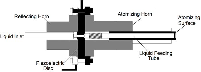
Figure 5: Nebulizers horn atomizer in which a liquid stream flows through a tube and then comes into contact with a transducer (Courtesy of Berger) [20].
Figure 6: Submerged nebulizers transducer for generation of droplets, The system shown call produce roughly 1g/h of submicron-sized powder with a gas-phase particle concentration of 106 to 107/cm3 [21].
The class of nebulizers atomizers relying on a capillary tube has been described by Berger [22]. As shown in Figure 5, the nozzle consists of piezoelectric transducers placed between a pair of sections of the horn. The surface on which the droplets are formed is at the end of the stem, Liquid is delivered through a tube to the transducers. These atomizers which rely on making a liquid come into contact with an exposed transducer operate in a similar manner. The maximum flow rate is typically 10 liter/h at 55kHz, whit a droplet or particle size range of 30 to 60μm. The output drops dramatically as the frequency increases. Nebulizers transducers that are submerged in a liquid provide some of the smallest droplets of all nebulizers atomizers. An example is shows in Figure 6. The submerged nebulizers transducer can provide 1 to 5μm droplets for frequencies of 1.5 to 2.4MHz with low gas flow rates that correspond to high droplet concentrations. In medical applications, these droplets, when inhaled, can penetrate deep into the lungs to deliver medication [19]. The major disadvantage of this type atomizer is the low liquid flow rates per transducer. Submerged nebulizers transducers have been used in a large number of studies of spray pyrolysis. Much smaller particles can he obtained with these nebulizers atomizer (typically, 2 to 4μm) than with the other nebulizers types, which produce droplets whit mass median diameters of 20μm and larger. The droplet size depends on the surface tension, density, and frequency of the nebulizers Source, according to the equation.
where d is the droplet diameter (cm), σ is the surface tension (erg/cm2), ρ is the fluid density (g/cm3), and ft is the transducer frequency (1/sec). Figure 7 show how median droplet diameter depend of the frequency [23]. Transducers with frequencies ranging from 1.6 to 2.4MHz are commercially available and produce droplets of 2 to 3 μm in median diameter. The primary advantages of nebulizers generator whit submerged transducers are:
1) Narrow droplet size distribution.
2) Simplicity.
3) High concentration of droplets.
4) Droplet size appropriate for spray pyrolysis.
5) Ability to vary droplet size by varying frequency.
Several studies have measured droplet size distributions [24,25]. Figure 8 shows droplet size distributions produced using this type of nebulizers generator [26]. The figure demonstrates that the droplet sizes required for most spray pyrolysis applications for powder generation correspond to frequencies near 2MHz. Droplet concentrations depend on the details of operation of the reactor, but typical values are 106 to 107 droplets/cm3.
Figure 7: Calculated dependence of droplet size on transducer frequency for generation with submerge nebulizers transducer.
Figure 8: Number (- - -) and volume (----) distribution of water droplets obtainers by nebulizers atomization (left) compared to number (- - -) and volume (---) distribution obtained by pneumatic atomization (right). Reprinted with permission from [26].
Nebulizers atomizers such as that shown in Figure 6 exhibit a dependence of the aerosol output on the level of the liquid above the transducer, as shown in Figure 9 [26]. This requires careful design of these atomizers to maintain a constant Liquid level. Such generators also exhibit a strong dependence of the aerosol output on the nebulizers power and gas flow. Typically, a certain gas flow is required to optimize the output in the sense that a maximum in aerosol concentration is obtained as the gas, flow rate is varied. This situation is illustrated in Figure 10 [26].
Figure 9: Measured dependence of aerosol flow as a function of level of liquid above transducer in system similar to that shown in Figure 6 [26].
Figure 10: Effect of
a) Nebulizers power level and
b) Carrier gas flow rate on nebulizers atomization of butanol.
Electrostatic Atomizers
Electrostatic atomizers exploit charges for generating and modifying droplets and their sizes. There are two types of electrostatic atomization. In the first type, the electrostatic forces are insufficient to influence the stability of the droplet or liquid stream. However, once produced by conventional means, the drops are given electric charges by corona or induction charging. These atomizers are also termed hybrid atomizers because the liquid is atomized using pressure, pneumatic, or rotary atomizers and the drops are charged after being formed. A typical median diameter for the drops they produce is in the range 30 to 50μm for a liquid flow rate of 50mL/min. These atomizers find applications where high droplet deposition efficiencies are needed. In the other type of electrostatic atomization, which has been studied extensively by aerosol scientists, the electrostatic forces by themselves are strong enough to atomize the liquid. Although the method is capable of producing submicron droplets, it does not yet allow simultaneous high liquid flow rates and droplets of that size [27-29]. As a result, it has been used primarily on the laboratory scale. A typical system for droplet generation is shown in Figure 11 [30]. This type of atomizer has been used extensively to form droplets that are deposited onto surfaces. A measured size distribution is shown in Figure 12 [31]. Electrostatic atomizers have the advantage that the charged droplet can be manipulated using electrical fields. This allows droplets to be deposited onto surfaces even in the presence of thermophoretic forces, which drive the particles away from a hot surface. Submicron-sized metal powders have been produce by electrostatic atomization of molten metal. Particles as small as 0.01μm and as large as 10 to 100μm have been generated. A facility with a large number of such atomizers can produce 1000 kg of powder per day [32].
Figure 11: Electrospray system for droplet generation [30].
Figure 12: Droplet size distribution obtained from electrospraying [31].
Summary of Atomizer Characteristics
Table 1 gives a summary of the characteristic of the various atomizers. An important conclusion is that only the submerged nebulizers, Collision-type, and electrospray atomizer are capable of producing droplets below roughly 10μm. Other atomizers with similar droplet sizes, based on other exist but are not commercially available.
Table 1: Atomizer characteristics.
Dry Powder Feeders
The dispersion of dry bulk powders into an aerosol stream has many applications, including inhalation studies, instrument calibration, aerosol characterization, drug delivery, and materials processing such as the classification of powder by particle size. The aerosolization of powders from bulk materials has been accomplished using fluidized beds and variation on power defers in combination whit jet mills and ventury-type powder dispersion devices [33-35]. The optimum aerosol stream generated with these devices is once that contains unagglomerated particles with a consistent and controllable instantaneous and time-integrated particle mass concentration particles mass concentration and throughput These stream characteristics depend primarily on the attributes of the powder that is generated, the device used to generated, the device used to generate the powders, and the operating parameters of the generating device. The dispersion characteristics of dry powders depend largely on the size, shape, and composition of the particles, the charging characteristics of the powder in the device, the extent of agglomeration of the particles in the powders, and the water absorption characteristics of the powder. In general, hydrophobic powders that are unagglomerated in the bulk disperse better into the powders, and the water adsorption characteristic of the powder. In general, hydrophobic powders that are unagglomerated in the bulk disperse into the gas than do agglomerated and hydrophilic powders, and dispensability increases with particle size. Fluidized-bed particle generators use the mechanical energy of fluidized beads to disperse small, micronsized particles. These generators consist of beads hundreds of microns in sizes that are loaded with the micron-sized particles to be generated. The mixture of beads and small particles is fluidized, and the small particles are released from the bed and carried off in the fluidizing gas. For a given powder, the mass output of the generator and the size of the particles generated are dependent upon the fluidizing gas the velocity, the bed height, and the mass particles relative to the mass of the beads [33]. Powder-feeder-airdispersion combinations use a mechanical dust-feeding mechanism such as a screw feeder or a scraper to feed the powder to a jet mill or venturi, where the particles are dispersed in a gas. For a given powder, the degree of dispersion and the mass output of the devices are dependent primarily upon the feed rate to the gas dispersion device and the gas flow characteristics in the device.
Droplet Impactors and Virtual Impactors
Inertial classification is a technique that can be used to remove larger droplets or particles from a gas stream by impaction on a surface or to remove smaller droplets or particle, while concentrating the remaining droplets or particles. For this reason, it is a powerful technique that has numerous applications in the processing of both films and powders. Inertial classifier, which include impactors, virtul impactors, and cyclones are widely used in the aerosol field, but also have seen limited applications in materials processing. Droplet impactors (Figure 13) rely on directing a gas stream towards a surface near which the gas stream turns, and the inertia of the large particle or droplet causes them to collide with the surface [36]. This is also the arrangement used for fabrication of films by droplet deposition (spray pyrolysis of films). Droplet impactors have been used and studied both theoretically and experimentally [37-44]. The studies provide excellent and useful guidelines for the design of systems for film generation by droplet deposition. Many versions of these devices are available commercially for collecting particles, and many more have been designed, built, and used in special studies of materials processing by aerosol routes. Particles as small as 1 nm can be collected using this technique. Virtual impactors (Figure 14) direct a gas stream towards an opening while drawing off most of the gas stream to the sides [45-48]. The larger particles are unable to follow the gas drawn off to the sides and therefore travel into the opening. As a result, the larger particles remain airborne and are concentrated in the small amount of remaining gas.
Figure 13: Impactor relying on inertial deposition of particles [36].
Figure 14: Virtual impactor relying on inertial separation of particles [47].
The feature of keeping the larger particles in the gas phase is important for further processing of the droplets or particles. Cutoff points (the diameter above or below which particles are retained or removed) can be as small as 1μm in practice. Cyclones (Figure 15) are also widely used to remove larger particles from a gas stream [4,49]. Cyclones rely on passing a gas tangentially into a cylindricalshaped container, resulting in a gas flow in the radial direction. The inertia of the particles causes them to collide with the walls, where they are captured. Cyclones can collect much larger quantities of particles than impactors can and, for this reason, are often used to collect particles from gas stream. Numerous models are available commercially. Cyclones are most effective for particles larger than a few micrometers in size. The inertial collection or particles relies on the momentum of the particles, Collection occurs by forcing the gas flow to make a sharp turn and then capturing the particles with sufficient inertia to cross gas streamlines that collide with the surface. Particles with less inertia remain in the gas flow and do not cross streamlines. A good example of inertial collection is an automobile moving down the highway. Insect do not usually hit the windshield at low speeds (relative to each other), but do so at high speeds. Large insects hit the windshield, while smaller insects do not. Finally, the bugs tend to strike region of the car where the flow of the air has to turn more sharply. This situation is quantified in terms of the Stokes number (Table 2).
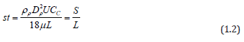
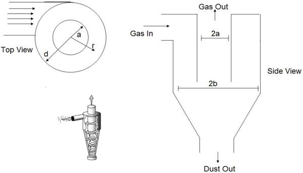
Figure 15: Cyclone relying on inertial classification [59].
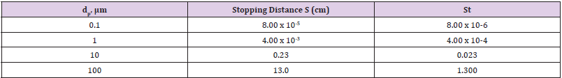
Table 2: Stopping distance of particle for length scale of 10cm.
Where S is the stopping distance (the distance a particle travels in a gas until in reaches zero velocity whit respect to the gas), ρ ρ is the particle density, dρ is the particle diameter, U is the velocity of the fluid, μ is the viscosity of the gas and L is a characteristics length of the flow geometry. It is useful to compare the operating principles of the different types of inertial devices. A conventional impactor (Figure 13) consists of a gas jet directed at a flat plate. Variations include either round or rectangular nozzles, single or multiple nozzles, and flat or cylindrical impaction surfaces. In a virtual impactor (Figure 14), the impaction plate is replaced by a collection tube, which is chosen to be larger than the jet. The larger particles travel nearly in a straight line into the collection tube, while the smaller particles leave with the majority of the gas flow. Only a small fraction (often just 10%) of the original amount of gas passes through the collection tube, thereby concentrating the particles. In a Cyclone, the aerosol stream is through an inlet and enters a cylindrical region tangentially at the outer edge of the cylinder, which is connected to a conical-shaped region. The gas spirals down the outer edge of the cylinder and cone walls and then reverses direction, after which it spirals upward along the center of the cyclone and exits through the top. The larger particles are collected on the cylindrical and conical walls by means of their inertial forces.
Agglomerates of impacted particles fall off the walls to the bottom, where they are collected. A major difference between virtual and conventional impactor is that particles smaller than the cutoff size of the virtual impactor remain in the both the major and minor flows. The small particles in the large-particle fraction can be eliminated by providing a central core of clean air in the nozzle of the impactor. Besides being an inertial classifier, a virtual impactor can be used to concentrate particles larger than the cutoff size. Because these particles are concentrated in the minor flow, the concentration factor is equal to the total flow rate the minor flow rate. Concentration factors of 20 can be obtained.
Powder Collection: Filtration and Electrostatic Precipitators
Separation of particles from gases is used for a variety of applications that consist primarily of the cleaning of gas for use (compressed air). The removal of particles in a process as waste of product, or the cleaning of the air in an enclosure (e.g., the removal of cigarette smoke from a room through filtration and air circulation units). The discussion in this section will concentrate on the removal of particles as a powder product from an aerosol process stream. The reader is referred to Willeke and Baron for an in-depth discussion [4]. Aerosol particles can be separated from a gas using sedimentation, centrifugal force, inertia, interception, electrostatic precipitation, diffusion, and thermophoresis (Figure 16) [50]. Although a large number of devices are available that use one or more of these mechanisms to collect particles from an aerosol stream, the most effective mechanism of powder collection depends primarily on the particle size distribution, the particle density, and the gas mean free path of the aerosol stream. In selecting a method for collecting powder, one must consider many aspects of the aerosol stream, because it is these features that will determine the most efficient method of particle collection. Among such features are the average particle size, particle size distribution, particle density, gas mean free path, and gas composition, chemical and physical properties of the powders, particle morphology, and end use of the powder. Other matters to be considered in selecting a powder collection device are the collection temperature, the mass loading of the aerosol stream, the stream flow rate, the desired collection efficiency, whether the particles or gas are corrosive, and even the value of the powder relative to the cost of the unit, all of which are related to the economics of the process.
Figure 16: Filtration efficiency curve for particle in a gas. Note that the efficiency is high for small particles because of diffusion collection, in contrast to particle in liquid, where the collection efficiency is lower that smaller particle [60].
These factors determine the type, size, and materials of construction of the powder collection device, which, in turn, determine the cost of the unit. In general, the smaller the particles , the higher the collection efficiency, the more corrosive the environment, the higher the collection temperature, mass loading, and gas flow rate, the more the powder collection unit will cost. Of course, special consideration should be given to each application and device. Devices used for particle collection include filters cyclones, settling chambers, electrostatic precipitators, thermophoretic collectors, scrubbers, impactors, and combinations of these devices. The most common type of collection devices are fillers, cyclones, settling chambers, and electrostatic collection devices, which are discussed in the remainder of this section.
Filtration
Filters can be designed for use in almost any application. For large-scale processes, filtration is generally more expensive than cyclones or settling chambers. Filters are commonly used, however, to collect particles with aerodynamic diameters less than 10 microns because these particles are difficult to collect using cyclones or settling chamber. During filtration, particles are collected primarily by impaction, interception, and diffusion onto the filter substrate (Figure 16). A common misconception is that small particles are difficult to collect from gases. This is true only for liquids; Figure 16 shows that smaller aerosol particles are collected more efficiently than larger particles once the size of the particles is below a few tenths of a micrometer. This occurs because of the relatively high diffusion coefficients of particles in gases. Depending upon the type of filter and the aerosol used, particles can penetrate the top surface of the filter and enter into the filter body. For the collection of a product power this is undesirable, as powder that enter the body of the filter cannot be recovered easily. For this reason, high surfaceloading filters are desirable when high recovery rates are required. Filters can be used to process streams with flow rates ranging from less than 1mL/min to many thousands of cubic feet per minute. The size of the filter unit required depends on the system requirements, such as the flow rate and the maximum allowable pressure drop across the filter, the pressure drop per surface area of filter per gas flow rate, the mass loading of the aerosol, and the physical properties of the powder. The permeability of the filter depends upon the type of filter used and the pore size of the filter. For a given type of filter, the smaller the pore size, the lower is the permeability of the filter, and the larger is the surface area of the filter required for a given gas flow rate and pressure drop across the filter. Normally, filters with higher efficiency have lower permeabilities; therefore, the more stringent the collection efficiency requirements, the larger the filter unit will be.
Small laboratory processes normally use plate filter, small cylindrical filters, or small bag filters. Large industrial-scale processes use baghouse filters, which are large housings that contain multiple banks of bag or cylindrical filters. Many types of filters have different efficiencies, permeabilities, corrosion resistances, temperature resistances, and surfaceloading properties, Some of the most commonly used filters for powder recovery on the laboratory scale are nylon, polysulfone, polycarbonate, polypropylene, polyethylene, metallic, ceramic and Teflon-based filters. A large number of baghouse filters also are available, ranging from simple polyester fabrics to stainless-steel mesh fillers and Teflon filters. In the removal of product powder, contaminates are undesirable; therefore, filters that do not flake off in to the powder are desired. As the filter collects particles on the surface, the permeability of the filter decreases; thus, the pressure drop across the filter increases. As different powders load up in different configurations on the filter, the amount of material that can build up on the filter before the powder is removed depends on the powder’s packing properties. In small-scale systems, once the filters are loaded with powder, they are normally removed and scraped to remove the powder, and then they are discarded. In large-scale processes, when the filters have been loaded with powder, the powder is normally discharged from the surface of the filter cartridges by shaking or purging the filter, from the inside out with gas that releases the powder, which then drops from the filters to a hopper, where it is collected in a bucket.
Cyclones
Cyclones operate on the principal of spiraling an aerosol gas through a cylinder, thereby imposing an artificial gravity on the particles, in a manner similar to a centrifuge, so that the particles are forced in an outward direction to be deposited on the inner wall of the cylinder [4]. Following deposition, the particles fall by gravity into the base of the cyclone, where they are collected in a pot. After the gas is spiraled through the centrifuge and the particles are collected, the gas exits the cyclone through the top of the cylinder. Both droplets and dry particles can be collected using cyclones. These devices are most efficient, however, at collecting particles that have aerodynamic diameters greater than 5 microns, although specialty cyclones can collect particles as small as 1 or 2 microns in diameter. Al the same time, good collection efficiencies in this size range are difficult to obtain, especially in larger cyclone. Cyclones are commercially available and can be designed to handle virtually any flow rate. They are perhaps the most economical and widely used powder collection devices available. Cyclones are normally constructed of metal and can be used at temperatures as high as 1000 °C. Advantages of cyclones over bag filters include less of a powder holdup, little or no increase in the pressure drop through the cyclone as powder is collected, simplicity in design and construction, the ability to process high-temperature gas streams, and relatively low cost. However, cyclone collection efficiencies for particles less than about 5 microns in diameter are often lower than those obtained using filters. Also, filters are usually much more forgiving in collection efficiencies for variation in flow rate. Cyclones can be placed in series or in front of other collection devices to reduce the material loading of the gas. When cyclones are used in series, they act as size classifiers by removing smaller and smaller particles in each successive step.
Settling Chambers
Settling chambers use gravitational settling of particles as a means of collecting them. The aerosol stream is sent into the base of a relatively large chamber, which is sized such that the upward velocity of the gas is smaller than the settling velocity of the particles. The particles thus settle out of the gas. Due to their mode of collection, settling chambers are used for particles with significant settling velocities or particles generally greater than 25 to 50 microns. The size of settling chambers depends on the settling velocity of the particles and the flow rate of the gas being processed, settling chambers can be used for both large-and small scale processes.
Electrostatic Precipitators
In electrostatic precipitators, charged particles are collected on an oppositely charged surface (Figure 17) [34]. this is accomplished by flowing an aerosol stream through an electrical field that ionizes the gas and creates a small electrical current from one plate lo another. The current exchanged between the oppositely charged surfaces depends primarily upon the composition of the gas, voltage potential between the charged surface and the distance between the surfaces. Normally the amperage between the plates is on the order of microamperes, and the voltage between the plates is tens of thousands of volts. If the gas breaks down, arcing between the charged surfaces will occur; this is not wanted because spikes in the amperage discharge are hard to deal with electrically, and the side receiving the discharge can develop pits. Also, the particle collection efficiency decreases drastically during arcing. For this reason, the operation characteristics of electrostatic precipitators are strongly dependent on the ionization potential of the gas. One of the main advantages of the electrostatic precipitator is that the collection efficiency of the particles actually increases with a decrease in size, due to an increase in particle mobility with decrease size [4]. Electrostatic precipitators are commercially available at the scale of most processes.
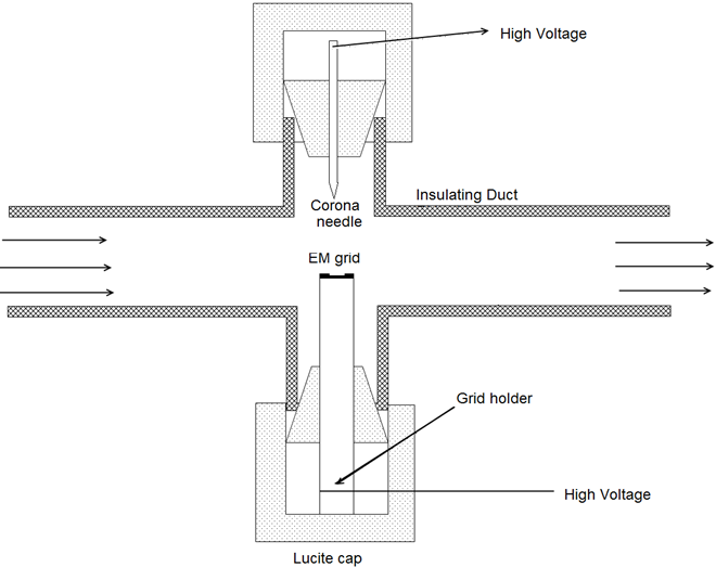
Figure 17: Electrostatic precipitation for sampling particles [34].
Volatile Reactant Delivery Systems
The delivery of volatile precursor, to a reactor can be accomplished by a variety of methods, which are primarily determined by the volatility and the chemical and physics properties of the precursor. This topic is discussed in detail elsewhere [3]. In general, gaseous reactants are easier to deliver than liquid precursors which, in turn, are easier to deliver than solid reactants. This is due to the volatility of the gaseous reactants and the associated simplicity of the vaporization equipment. Generally, a continuous and consistent precursor output is desired and controlled precursor mass loading and mass flow rates are a necessity. Additionally, case and accuracy of determining and controlling the mass output of the precursor is beneficial. Special considerations neck to be taken for each reactant. For example, reactants that are sensitive to certain environments (such as air or moisture) must be stored and delivered in environments that do not degrade the precursor. Also, the thermal stability of precursors can limit the time and temperature at which they can be heated. As an example, Figure 18 shows the evaporation rates of a solid precursor as a function of time at different temperatures [51]. The rate drops with time because of changes in precursor characteristics such as surface area and degree of degradation by solid-state reactions. In some instances, special techniques such as spraying are required to deliver thermally unstable precursors [51].
Reactants that are already in a gaseous state such as saline or ammonia, can be delivered and regulated relatively easily by using a pressurized gas cylinder, a pressure regulator, and a flowmeter assembly that is resistant to chemical attack by the gas. Gases are the most convenient form of precursor to deliver, because they are easily delivered in a continuous and consistent stream that can be controlled and monitored. Liquid reactants are normality generated using hobblers, evaporation pots, below-saturation- Level evaporation chambers, specialized liquid delivery systems, or spraying equipment such as nozzles or nebulizers. In standard bubblers, a carrier gas is bubbled through the liquid, thereby facilitating the evaporation of the precursor into the carrier gas. For a given precursor, the amount of precursor evaporated is dependent upon the temperature of the bubbler (which controls the vapor pressure of the precursor), the gas flow rate through the bubbler, the pressure of the bubbler (vacuum or pressurized), and the saturation level of the gas exiting the bubbler. Bubblers are perhaps the easiest and most common method of delivering volatile liquid precursors on a laboratory scale. The vapor production characteristics of bubblers are usually very good, and the mass output of bubblers can be easily monitored through changes in their volume or weight.
Evaporators are containers of the volatile liquid or solid precursors that are open to the system. Most often, evaporators are used on processes that operate under vacuum, and no carrier gases are used. However, evaporators can also be used in high-pressure systems if the precursor is volatile enough to deliver the reactant at the required rate. In evaporators, the precursors simply evaporate and expand into the system. The evaporation rate is a function of the precursor vapor pressure, the system pressure, and the evacuation rate of the system. These parameters can be controlled by varying the temperature of the evaporator and the system pressure. Quite often, the vapor pressure of the precursor sets the pressure of the system. Liquid delivery systems are similar to evaporators, except that the precursor (usually a liquid) is delivered to the evaporation chamber in a controlled fashion. (The mass throughput of the liquid is controlled.) The evaporation chamber is operated at a temperature such that the precursor immediately evaporates. With this method, the precursor delivery rate is controlled by the feed rate to the evaporation chamber. A liquid delivery system can be used for pure liquids, solutions, or solids, although the delivery of liquids is much easier than that of solid reactants. Liquid reactants can be delivered to the evaporation chamber by a pump or a spray. A spray is often better because it facilitates more efficient evaporation. Solids can be delivered with a dry powder dispenser or by dissolving the precursor in an inner solution spraying the solutions into a chamber where it evaporates. Spraying solid precursor solutions is not always possible, because few solvents are compatible with both the precursor and the process itself. Still, the approach is valuable for precursor that are thermally unstable: The precursor does not have to be heated for extended periods of time and is heated and evaporated only as needed.
Solid reactants are usually the most difficult precursors to deliver at a consistent vapor feed rate.
The simplest method for delivering solids is to flow gas over a heated bed of the solid reactant. However, the vaporization rate of the precursor can vary greatly, as the saturation level of the gas is dependent upon the surface area of the powder, which changes as it evaporates (Figure 18). One method of getting around this problem is to provide a large amount of powder surface area, so that the carrier gas always gets saturated in the evaporator or the surface area of the precursor powder changes very little with time. A method for accomplishing this is to provide a packed bed of the precursor and a high substrate surface area, such as beads, and then flow the carrier gas through the packed bed as in Figure 19 [52]. For this case, channeling through the bed must avoided. As discussed previously, solid reactants can also be delivered by spraying solutions or by using evaporators. Dissolving the solid reactant in a liquid and spraying the solution into an evaporation chamber is advantageous because the delivery rate is controlled and steady. However, as mentioned before, solvents that are compatible with the process and the precursor are not always available. Finally, reaction-based vapor generators that take advantage of the reaction of two or more bulk materials to generate the desired volatile reactant are sometimes used. Usually, a solid and a gas are reacted to give off a volatile precursor, as is done in the production of Ti02, wherein raw rutileore or titanium metal is reacted with chlorine gas to form a gaseous TiCl4, which is purified and delivered to be processed. In using this type of vapor generator, is often advantage to have the gas feed stream rate be limiting such that the delivery of the vapor precursor is regulated by the amount of gas fed into the generator.
Figure 18: Evaporation rates of Ba(thd)2 as a function of time: P= 0 torr, Q = 34.65 sccm. Curves are drawn on te basis of fifted empirical equation [61].
Figure 19: System for generating AlCI3, vapor for introduction into a gas-to-particle conversion reactor [62].
Nebulizers Spray Pyrolysis
In the nebulizers spray pyrolysis system [53], a geyser is formed in the liquid surface by the action of a beam of nebulizers vibrations which is directed to a liquid-gas interface. This geyser is followed by the generation of a spray formed by microscopic droplets. A carrier gas transports and directs the spray toward the surface of a hot substrate where the film formation is produced (Figure 20).
Figure 20: System for generating AlCI3, vapor for introduction into a gas-to-particle conversion reactor [62].
Nebulizers Atomization
The nebulizers irradiation of a liquid with excitation potentials above a threshold value, results in the atomization of the liquid into microscopic droplets which forms a spray. The average diameter of the droplets generated by the nebulizers beam (D) depends directly on the wavelength (λc) of the nebulizers signal in the solution [53]:

where α is a constant.
Using the Kelvin equation [54], the nebulizers signal length in the solution can be written:
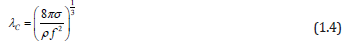
where: represents the surface tension of the liquid, the liquid density, nebulizers excitation frequency. An experimental determination of the value of the constant [55] is 0.34 which allows expressing the average droplet diameter as:
The above equation shows clearly that the average diameter of the generated droplets (D) depends on the nebulizers excitation frequency, and on the characteristics of the irradiated liquid (surface tension and solution density).
The main parameters in the nebulizers atomization are [53]:
1) Nebulizers Power: Once generated over a threshold value, the amount of spray is continuously increasing as a function of the power applied to the ceramic. This parameter can control the amount of spray generated. Figure 10a shows the power effect of the nebulizers source in the nebulizers atomization of a butanol solution.
2) Frequency of Excitation: The excitation frequency of the ceramic must be close to the resonance frequency of the molecules forming the precursor solution, this in order to optimize the atomization.
3) Carrier and Director Gases: The director gas leads the spray to the substrate in which the film is deposited. The spray flow rate is a function of the flow rate of the carrier gas. These parameters also allow control the rate of flow of spray. Figure 19 shows the effect of carrier gas flow in the nebulizers atomization of a butanol solution.
4) Fluid Level in the Atomization Chamber: For each liquid being atomized and taking into account the geometry of the atomizing chamber prepared according to the geometry of the nozzle and its separation distance from the substrate (Figure 20) a liquid level h0 is calculated, which corresponds to the maximum amount of spray generated. Figure 19 shows the effect of the liquid level h0in the atomization chamber in the nebulizers atomization of a butanol solution [56-65].
5) Precursor Solution: As mentioned above the physical properties of the solution (surface tension and density of the solution) play an important role in the nebulizers atomization model.
Acknowledgment
The authors gratefully acknowledge the financial support from the Escuela Superior de Medicina, Instituto Politécnico Nacional, through Project no. 20210385.
References
- Bayvel L, Orzechowski Z (1993) Liquid Atomization. In: Bayvel L, Orzechowski Z (Eds.)., Taylor and Francis, Washington, USA.
- Lefevre AH (1989) Atomization and Sprays. In: Lefevre AH (Edt.)., Hemisphere Publishing Co, New York.
- Kodas TT, Hampden Smith (1994) The Chemistry of Metal. In: Kodas TT, Hampden Smith (Eds.)., CVD Weinhein, VCH, Verlagsgesellschaft, West Germany.
- Willeke K, Bmoll PA (1993) Handbook of Aerosol Measurement: Principles, techniques and Applications. In: Willeke K, Bmoll PA (Eds.)., Van Nostrand Reinhold, New York.
- See JB, Johnston GH (1978) Powder Technol.
- Roylance TF, Pickering SJ, Hay N, Thomas GH (1985) A rotary cup air blast atomizer for molten slag- an investigation of particle size and spray trajectory. Institute of Energy, ICLASS-85, 3rd International Conference on Liquid Atomization and Spray Systems at Imperial College, London, p. 1-16.
- Smith NP, Norris JOW, Hemsley DL, Yeoman ML (1985) Measurement of the size and velocity of liquid metal drops during atomization. 3rd Conf. on Liquid Atomzation and Spray Systerms, Imperial CoIlege, London, p. 1 -9.
- Salisbury CL, Tuncel G, Ondov JM (1991) Aerosol Sci Technol 15: 156-169.
- May KR (1973) The collison nebulizer: Description, performance and application. J Aerosol Sci 4(3): 235-243.
- Mercer TT (1973) Aerosol Technology in Hazard Evaluation. In: Mercer TT (Edt.)., Academic Press, New York 5(11): 402.
- Messing G (1994) Nano particulates Workshop Monterey CA.
- Denton MB, Schwartz DB (1974) Rev Sci Intrum 45(1): 81-83.
- Goddard RF, Mercer TT, Oneill PXF, Flores RL, Sanchez RJ (1968) Output Characteristics and Clinical Efficacy of Ultrasonic Nebulizers. Asthama Research 5(4): 355-368.
- Lang RJJ (1962) Ultrasonic Atomization of Liquids. Acoustical Soc Am 34(1): 6-8.
- Lierke EG (1967) Nebulizers, pp. 214-218.
- Perron RR (1967) I.E.E.E. Trans. Sonics and NebulizerssSU-14(4): 149-153.
- Peskin RL, Raco RJJ (1963) Ultrasonic Atomization by Difference between Vibration Displacements of Two Circular Vibrating Plates. Accoustical Soc Am 35(9): 1378-1381.
- Pointon AJ (1982) I.E.E.E.Proc. 129: 285-307.
- Topp MN, Eisenklam P (1972) Nebulizers, pp. 95-101.
- Berger HL (1985) Characterization of a Class of Widely Applicable Nebulizers Nozzle. Proc. 3rd Con. On Liquid Atomization and spray systems, London.
- Lyons SW (1992) Aerosol dynamics of superconducting ceramic power Generation by Gas-Pase Process. Master´s thesis, university of New Mexico.
- Berger HL (1985) Proceeding of the 3rd Int conf. on liquid atomization and Spray System. In: Berger HL (Edt.)., Conference publication, London, p. 1-13.
- Tang Q (1992) Aerosol-deposited YBaCuO thin films and superconducting optical detector. Ph. D. dissertation, Twente University, Enschede, the Netherlands.
- Rodes C, Smith T, Crouse R, Ramachandran G (1990) Measurements of the Size Distribution of Aerosols Produced by Ultrasonic Humidification. Aerosol Sci Technol 13: 220-229.
- Tarr MA, Zhu G, Browner (1999) Applied Spectroscopy 45(9): 1424-1432.
- Langlet M, Joubert JC (1993) Chemistry of Advanced Materials. In: Roa CNR (Edt.)., Oxford Blackwell Scientific Publication, UK, p. 55.
- Graf PE (1962) Breakup of small liquid volume by electrical charging. Proceedings of API Research Conference on Distillate Fuel, New York: Am. Petroleum Institute 1710: 62-64.
- Luther FE (1962) Electrostatic automization of No. 2 heating oil. Proceedings of API Research Conference on Distillate Fuel, New York: Am Petroleum Institute 1710: 62-63.
- Meesters GMH, Vercoulen PHW, Marijnissen JCM, Scarlett BJ (1992) Aerosol Sci 23(1): 37-49.
- Rosell Lompart J, Fernandez de la Mora JJ (1994) Charge and Size Distributions of Electrospray Drops. Aerosol Sci 186(2): 280-293.
- Naqwi AA (1994) In situ measurement of submicron droplets in electrosprays using a planar phase Doppler system. J Aerosol Sci 25(6): 1201-1211.
- Bailey AG (1986) Atomization Spray Technol 2: 45.
- Carpenter RL, Yerks K (1980) Calibration of Aerosol Instruments. Am Ind Hyg Assoc J 41: 449-454.
- Hínds WC (1982) Aerosol technology : properties, behavior, and measurement of airborne particles. Aerosol Technology Wiley Interscience, New York.
- Koch W, Lodding H, Oenning G, Muhle H (1986) J Aerosol Sci 17(3): 499-504.
- Marple V, Rubow K, Olson B (1936) In: Willeke K, Baron PA (Eds.)., Handbook of Aerosol Measurement: Principles, Techniques and Application, Van Nostrand Reinhold New York, pp. 206.
- Biswas P, Jones CL, Flagan RC (1987) Distortion of size distributions by condensation and evaporation in aerosol instruments. Aerosol Sci and Technol. Aerosol Sci Tech 7(2): 231-246.
- Burton RM, Lundgren DA (1987) Wide Range Aerosol Classifier: A Size Selective Sampler for Large Particles. Aerosol Sci Tech 6: 289-301.
- Her JY, Kim SS (1991) Aerosol Sci Tech 14: 157-164.
- Hillamo RE, Kauppinen El (1991) On the Performance of the Berner Low Pressure Impactor. Aerosol Sci Tech14(1): 33-47.
- Marple VA, Olson BA (1995) A low-loss cascade impactor with stage collection cups: Calibration and pharmaceutical inhaler applications. Aerosol Sci Tech 22(1): 124-134.
- Merecer TT, Stafford RG (1969) Impaction from round jets. Am Occup Hyg 12: 41-48.
- Ranz WE, Marshal WR (1952) Evaporation from Drops. Chemical Engineering Progress 48(4): 173-180.
- Regtuit HE, DeRuiter CJ, Vrins ELM, Hofschreuder P, Oeseburg F, et al. (1990) Aerosol Sci 21(7): 919-923.
- Anderson TL, CharIson RL, Covert DS (1993) Calibration of a counter flow virtual impactor at aerodynamic diameters from 1 to 15μ Aerosol Sci Technol 19(3): 317-329.
- Biswas P, Flagan RCJ (1988) The particle trap impactor. Aerosol Sci 19(1): 113-121.
- Chien H, Lundgren DA (1993) A Virtual Impactor with Clean Air Core for the Generation of Aerosols with Narrow Size Distributions. Aerosol Sci Technol 18(4): 376-388.
- Chen BT, Yeh HC, Cheng YS (1985) A Novel Virtual Impactor: Calibration and Use. J Aerosol Sci 16(4): 343-354.
- Friedlander SK (1977) Smoke, Dust and Haze. In: Friedlander SK (Edt.)., Wiley Interscience, New York.
- Lee KW, Ramamurthi M (1993) In: Willeke K, Baron PA (Eds.)., Handdoook of Aerosol Measurement: Principles, Techniques and Applications. New York: Van Nostrand Reinhold, pp. 179.
- Chou KS, Tsai G (1994) J Thermochim Acta 240: 129.
- Powell QH (1995) Gas-phase production and coating of titiania in tubular, hot-wall reactors. Master’s thesis, university of New Mexico.
- Langlet M, JC Joubert (1973) The Pyrosol Process or the Pyrolysis of an Nebulizersally Generated Aerosol Chemistry of Advanced Materials.
- Rayleigh JWS (1945) The Theory of Sound. In: Rayleigh JWS (Edt.)., Enlarged Dover Publications, New York, US.
- Lang R J (1962) Ultrasonic Atomization of Liquids. J Acoust Soc Am 34: 6.
- Chen BT, Yeh HC, Johnson J (1985) Aerosol Sci 16(4): 343-354.
- Forney LJ, Revernhall DG, Lee SS (1982) Environ Sci Technol 16(8): 492.
- Friedman W, Willeke K (1986) Flow and pressure balancing in a fluid interface impactor. Aerosol Sci Technol 5(4): 447-457.
- Keskinen J, Janka K, Lehtimak M (1987) 6: 79-81.
- Novick VJ, Alvarez (1987) JL Aerosol Sci Technol 6: 63-70.
- Pillai RS, Yeates DB, Eljamal M, Miller IF, Hickey AJ (1994) Generation of concentrated aerosols for inhalation studies. J Aerosol Sci 25(1): 187-197.
- Rader DJ, Marple VA (1985) Effect of Ultra-Stokesian Drag and Particle Interception on Impaction Characteristics. Aerosol Sci Technol 4(2): 141-156.
- Ravenhall DG, Forney JL, Hubbard AL (1982) J Colloid Interface Sci 85(2): 508-520.
- Sioutas C, Koutrakis P, Burton RM (1994) Particle loss in glass honeycomb denuders. J Aerosol Sci 25(7): 1321-1330.
- Sioutas C, Koutrakis P, Olson BA (1994) Development of a low cutpoint virtual impactor Aerosol Sci Technol 21(3): 223-235.
