Impact Factor : 0.548
- NLM ID: 101723284
- OCoLC: 999826537
- LCCN: 2017202541
Bumkyoo Choi*1, Jaehyuk Choi1, Hyeong-un Kim2, Seok-soon Yi2, Yeon-mi Yang2 and Yasushi Mitani3
Received: January 19, 2018; Published: January 31, 2018
Corresponding author: Bumkyoo Choi, Mechanical Engineering, Sogang University, Seoul, Korea, 35 Baekbeom-ro, Mapo-gu, Seoul, 04107, Korea
DOI: 10.26717/BJSTR.2018.02.000707
Purpose: This paper presents the effectiveness of RAMPA (Right Angle Maxillary Protraction Appliance) system, i.e. RAMPA combined with ROA (RAMPA Oral Appliance), on human maxillae by analyzing the deformations from protraction forces with finite element method. In addition, the dimensional changes of the upper airway, skeletal facial and hyoid position changes by using cone-beam computed tomography in patients who were treated with RAMPA therapy were assessed clinically.
Methods: Using the integrated modeling that combines the 3D Scan file of the skull model with RAMPA structures designed in SolidworksTM, the amount of displacements has been calculated and the effect of RAMPA on the human skull has been analyzed quantitatively. The three types of forces were applied and the displacements were calculated and analyzed. For 6 patients with a mean age of 8.3 years (range, 7~10 years) who were treated with RAMPA therapy, CBCTs were taken before and after treatments and the images were measured by InViv TM (Anatomage) software, and analyzed.
Results: RAMPA rotates the patient's maxilla and mandible in the forward direction and forces them to move upward. After RAMPA treatments, there were significant increase of retroglossal and total airway volume (P<0.05). The horizontal. DH and C3-H, which indicate the anterior position of the hyoid bone, were increased and HyS and vert. DH, which represent the vertical facial dimension, was decreased after treatment.
Keywords: RAMPA; Protraction; FEM; Airway; Hyoid Bone
Maxillary bone is important both for aesthesis of the face and functions of speech, swallowing and mastication. In order to treat the maxillary hypoplasia, maxillary expansion devices have been developed since Angell introduced in 1860 [1]. There are rapid maxillary expansion (RME), slow maxillary expansion (SME), and semi-rapid maxillary expansion (sRME), which have been most commonly used for intraoral devices in this group. In general, RME therapy aims to treat young patients with maxillary deficiency and/or skeletal Class III malocclusion by applying a strong lateral force on the maxillary alveolar dentition to increase the dental arch width. Slow maxillary expansion (SME) is a treatment that attempts to solve the side effects of RME treatment by gradually expanding the maxilla by applying less force than RME therapy. In 1977, Mew announced semi-rapid maxillary expansion (sRME) as a remedy for the disadvantages of the aforementioned RME and SME therapies [2]. Generally, SME therapy is controlled at a rate of 1/3mm per week, RME therapy is at a rate of 3mm per week, and sRME regulates the patient at a rate of 1mm per week. His research has demonstrated that sRME therapy is sufficiently effective compared to RME therapy and can be a treatment complementing the shortcomings of SME and RME treatments [3,4]. As for extraoral appliances, chin cup, headgear, face mask, etc. have been used [5-12].
Previous studies reported that the maxilla was deformed anteroinferiorlyand the mandible was deformed downward after RME treatments. In addition, as for the extraoral device, it was only part of the role of assisting RME. This is a natural consequence of the fact that gravity works and a crucial effect on the treatments. Therefore, there is a need for an apparatus that overcomes gravity and exerts the anterosuperior force. In this study, we aim to overcome the gravity by simultaneously applying both intraoral and extraoral devices, to establish the correct occlusion by applying continuously the anterior-superior protraction on the maxilla. Especially, because any alteration in the position of the hyoid bone is an important factor for diagnosing patients, the results before and after RAMPA treatments were shown and discussed. Although previous studies showed that changes in hyoid bone position are related to changes in mandibular position [13-17] and that the hyoid bone adapts to antero posterior changes in head position [18], they did not the actual way of activating the anterosuperior protraction force. Assessment of the upper airway dimension has become an important diagnostic test in several subspecialties of dentistry, due to the potential effect of high airway resistance contributing to abnormal growth pattern, resulting in increasing vertical face dimension in child. In addition, the position of the hyoid bone is used as an important diagnostic tool for lowered tongue posture and mouth breathing.
We propose a method to connect the intraoral device, ROA, with RAMPA, which is an extraoral device, to continuously perform the sRME treatment and the maxillary protraction at the same time, and to assess the dimensional changes of the upper airway, skeletal facial and hyoid position changes by using cone-beam computed tomography in patients who were treated with RAMPA therapy.
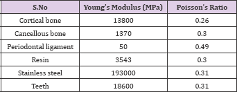
In order to quantitatively evaluate the effects of orthopedic treatment, finite element analysis was performed using a skull model from 3B Scientific® Biologia was scanned. For the comparison with the clinical results, the skull was set to the approximately same size of children's head of 8.3 years old. RAMPA was designed as the 3-dimensional structure in Solidworks™ as shown in (Figure1a). After combining the skull with RAMPA, they were imported to ANSYS Workbench. The materials were used for the finite element analysis and the values of mechanical properties were utilized from the previous study [19] as listed in (Table 1). In addition, a number of assumptions were made as follows;
Figure 1: RAMPA; a, Actual RAMPA installed on a skull model; b, RAMPA modelling for finite element analysis F1, The horizontal force F2, The front-vertical force F3, The rear-vertical force.

Table 1: Material Properties.
a. Linearly elastic and isotropic behavior for the bones was assumed.
b. The entire sutures behave in an elastic manner.
The three types of forces applied from RAMPA on ROA are shown in (Figure 1b). ROA is connected with RAMPA through AB as shown in (Figure 2). The directions of forces activated are shown in (Figure 3). Each type of force was applied symmetrically to both sides with respect to the center line of the nose. In other words, the forces exerted on RAMPA consist of six different forces. The loading conditions were set up by these six forces. The RAMPA system consists of ROA, and Active Bow (AB) connecting RAMPA as mentioned above. The maxillary bone should be towed anterosuperiorly against gravity due to the elastic force of the system, which is the protraction force. ROA is the device that covers the midpalatal surface with hard acrylic resin, which is used for semi rapid expansion.As for the direction of the horizontal elastic force of the RAMPA is applied approximately 10mm above and parallel to the midpalatal plane. (Figure 1b) shows the forward force vector (FJ and the upward force vectors (F2 and F3) by elastic rubber bands. Force F1 pulls the palate forward and upward, but at the same time force F2 pulls it upward and thus the front teeth could not be extruded.
Figure 2: ROA (RAMPA Oral Appliance); a, ROA installed under a palatine; b, ACTIVE BOW (AB) connecting RAMPA and ROA.

Figure 3: ROA (RAMPA Oral Appliance); a, ROA installed under a palatine; b, ACTIVE BOW (AB) connecting RAMPA and ROA.
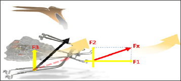
F3 is a towing vector rotating palatal plane (ANS-PNS) forward, which is one of most important vectors in the RAMPA system. This system rotates the palatal plane in the forward direction while the palate is pulled antero superiorly, resulting in the mandible rotating in the forward direction and growing in the horizontal direction. The ratio between the traction forces F1, F2 and F3 depends on the condition of the patient, but it is generally preferable that F1: F2: F3 be 2: 1: 3, which is much important. The equipment used in this study can be used in patients with mixed dentition and permanent dentition and the ranges of the traction forces, F1, F2, and F3, are 300-350g, 150-200g, and 350-500g, respectively. The wearing time should be more than 12 hours a day to be effective.
Subjects: 6 patients with a mean age of 8.3 years (range, 7-10 years) who were treated with RAMPA therapy.
CBCT were taken before and after the RAMPA treatments and the images were measured by InVivo ™ (Anatomage) software in terms of changes of the volume on the retropalatal and retroglossal airway [Threshold: Lower(-1000) ~ Upper(-500)]. The horizontal and vertical positions of the hyoid bone were measured using the sagittal view of the CBCT. The data of before and after the treatment were statistically analyzed with Wilcoxon signed rank test.
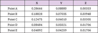
The results were shown for palatine bone at the points called the landmarks as in (Figures 4-8), which were used as in the previous orthodontics researches [20-22] for reliable data analysis. The results for the marked points (A, B, C, D, and E) of the midpalatal plane are shown in (Table 2). The 3-dimensional coordinates are X, transverse plane; Y, sagittal plane; Z, vertical plane.In the transverse plane, the midpalatal suture had the maximum displacement at the most front (point A) and was deformed in the opening direction, but the differences were little. This is also because of contraction of the palate from the forces exerted by RAMPA. In the sagittal plane, all midpalatal suture points showed forward movement, but the differences were little. Vertically, all of them had upward movement, which shows the antero superior protraction from RAMPA. For the results of the alveolar bone from midpalatal expansion, the displacement became larger in the posterior than in the anterior areas in the transverse plane, but the differences were little. This is because the external force exerted by RAMPA has the effect of tightening the dental arch of the palate. Sagittally, larger displacements occurred forward at the incisors, the canines, and the premolars were displaced forward. Vertically, the alveolar bone at teeth around molars was intruded, which was due to the upward force applied from RAMPA. (Figure 5) shows the Z-directional displacement distribution for the upper maxillary bones.
Figure 4: Important points for analyzing displacements and stresses; A, Point near the incisive foramen; E,point near the palatine bone; B, C, D points divide the A-E line into 4 quarters.
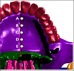
Figure 5:Z-axis directional deformation (mm) after activation of RAMPA.
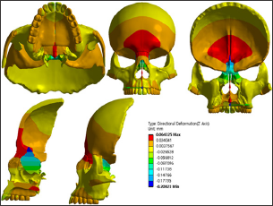
Table 2: Midpalatal suture displacements (mm) with RAMPA.
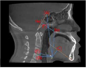
As mentioned above, the effect of RAMPA on maxillae is the anterosuperior protraction leading to the forward rotation of maxillary bone and mandibular bone, which results in more spacious upper airway and affecting the position of hyoid bone. In order to see the effects on various phenomena including volume of the upper airway and the position change of hyoid bone. (Figure 6) shows the planes defining the upper airway. Total upper airway volumes are composed of retropalatal volumes and retroglossal volumes as shown in (Figures 7 & 8). Shows how to define the position of hyoid bone and measure the change of the position. After RAMPA treatments, there were significant increase of retroglossal and total airway volume (P<0.05) as listed in (Table 3). In addition, the horiz.dH and C3-H, which indicate the anterior position of the hyoid bone, increased and HyS and vert.dH, which represent the vertical facial dimension, decreased after treatment. However, in the case of the position change of hyoid bone, little effect was shown because of short period (avg. less than 6 mos.) of RAMPA therapy because more than a year or two would be needed for shifting the positon of hyoid bone.
Table 3: Results of pre-and post-treatment CBCT analyses.
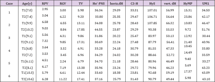
Note: *RPV(retropalatal airway volume, cc), RGV(retroglossal airway volume, cc), TV(Total airway volume, cc), UM1(width between maxillary first molars, mm).
Figure 6:The planes defining the upper airway;
a. A FH plane;
b. B Border of retropalatal and retroglossal airway section (Anterior lowest point of C1~PNS);
c. C Inferior plane (Plane that is parallel to FH plane on anterior lowest point of C3);
d. D Anterior border (Plane that is vertical to FH plane on PNS);
e. E Superior plane (Plane that is parallel to FH plane on the ˝ point of (D) line).
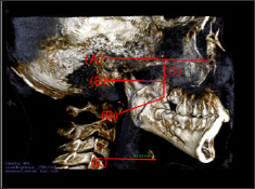
Figure 7:Threshold set-up & Segmentations of the airway;
a. Threshold set-up [Threshold: Lower (-1000) ~ Upper (-500)];
b. Total upper airway volume(TV): E plane to C plane;
c. Retropalatal airway volume (RPV): E plane to B plane;
d. Retroglossal airway volume (RGV): B plane to C plane.
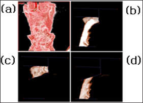
Figure 8:The measurement defining the position of hyoid bone;
a. HyS: linear vertical distance from Hy (uppermost point of the hyoid) to S;
b. vertical dH: linear vertical distance from H (most anterior point of the hyoid) to the PNS;
c. HyMP: vertical distance from Hy to the mandibular plane; vv
d. horiz.dH: linear horizontal distance from H to the posterior wall of the hypopharynx,
e. C3-H: linear measure from the H to the most anterior and inferior point of C3;
f. Ho’-PNS: linear measure from Ho' to PNS; Ho': Intersection of S-Ba with a line perpendicular to S-Ba registered on PNS.
In this paper, RAMPA and skull models were used to perform FE analysis. The deformation data was analyzed to investigate the effect of RAMPA. In the maxillary bone, deformation seems to occur in an upward direction and rotates in the forward direction. The results of this study not only demonstrate the potential of utilizing an engineering analysis to assess the efficacy of devices such as RAMPA but also illustrate the mechanical basis for the device. Also, the results from this study reveal that RAMPA rotates the patient's maxilla and mandible in the forward direction and forces them to move upward unlike other conventional maxillary protraction systems which rotate the patient's maxilla and mandible in the clockwise direction and pull them downward. In addition, RAMPA therapy has great effects on the upper airway volume and the position of hyoid bone. Retroglossal and total airway volume increased after RAMPA treatment. These changes should be accessed through a three-dimensional analysis rather than a two-dimensional analysis later. The position of the hyoid bone shifted horizontally forward and vertically upward, indicating that RAMPA treatment did not cause the increase of vertical facial dimension because of insufficient period. We concluded that RAMPA treatments can increase airway patency in the patients with airway space deficiency problem and redirect the vertical growth of face to horizontal growth.The position of hyoid bone relative to the cervical vertebra is very important for comfortable breathing. The results will be afterwards utilized in studying the relationship between position of hyoid bone and good posture of human body from the therapy.


