Impact Factor : 0.548
- NLM ID: 101723284
- OCoLC: 999826537
- LCCN: 2017202541
Angel F Farinas*, Kevin Saladino, Alonda C Pollins MLI, Nancy L Cardwell BS and Wesley P Thayer
Received: December 11, 2017; Published: February 05, 2018
Corresponding author: Wesley P Thayer, Department of Plastic Surgery, Vanderbilt University Medical Center, Nashville, USA
DOI: 10.26717/BJSTR.2018.02.000728
Background: Creating a barbed sutureless coaptation device will provide a simple and standardized alternative to nerve repair decreasing donor's morbidity.
Methods: Autodesk Fusion 360 program was used to design the prototype and was produced on a Monoprice Maker Ultimate 3D Printer A total of 89cm of caprine and canine vagus nerve were harvested, trimmed at 4cm segments and divided in four groups depending on the device used or intervention: Hollow, Ridged, Sutured and Barbed. An Instron 5542machine was used to calculate the energy at break (gf/mm).
Results: The energy at break of the Hollow group was 41.23 (±5.00) gf/mm, more than double for the Ridged: 107.024 (±29.06) gf/mm, and even higher for the Sutured: 392.69 (±66.24) gf/mm. But the Barbed group outperformed all groups with 1227.36 (250.88) gf/mm, with no statistical significance when compared the suture group (p>0.05).
Conclusion: The Barbed device was more resistant than the other groups in maintaining the nerve in position. Our prototype has the potential to become a viable alternative to peripheral nerve repair due to its ease of application and lack of a need for microsurgery for coaptation.
Keywords: Coaptation; Suture-Less; Conduit; Bioprinting; Barbed
Damage to peripheral nerves due to either traumatic injury or oncologic resection can create devastating functional deficits [1]. Current strategies for peripheral nerve repair rely on regeneration or proximal outgrowth aided by microsutures, nerve grafts, or manufactured conduits [2,3]. However, even after repair, it can take months for regenerating axons to reach denervated target tissues when injuries are proximally located [1,4]. This inability to rapidly restore the loss of function after axonal injury often results in poor clinical outcomes [5]. In fact, for some traumatic extremity injuries, the expected poor recovery of nerve function is often an indication for completion amputation over replantation [4]. Optimal results occur with primary end-to-end neurorrhaphy, performed in less than 72 hours and requiring an intimate knowledge of the relevant anatomy and pathology [1]. However, this treatment is not always an option depending on the type and location of the injury. With gap injuries, excessive tension prevents direct epineural repair, creating a need for autografting or allografting when donor nerve is unavailable [6]. The availability of a surgeon with the requisite knowledge and experience to delicately perform the repair can be a significant limiting factor in some parts of the world and even our country. For these reasons, we set out to develop a novel device/ system using suture-less coaptation for simple and effective nerve repair after injury including segmental nerve defects, in which any surgeon despite their specialty can promptly perform peripheral nerve repairs with positive outcomes and saving precious operative room time for other concomitant injuries that need more attention [7]. It was determined that 3D printing would be a relatively quick way to manufacture a series of devices for our pilot testing. Threedimensional bio-printing has emerged as a dynamic and tunable alternative to traditional biomaterials for tissue engineering [8,9]. Advancements in the field have led to astounding results mostly within the last decade. For the purposes of this study, we barely brush the surface of the three dimensional printing world, but it is enough to prove that this is worth further exploration.
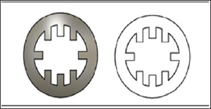
The nerve coaptation device was designed using Autodesk Fusion 360. The original design comprises a hollow cylindrical tube consisting of barbs angled inward (Figure 1). The barbs on the inside of the tube angle towards the midpoint of the tube in order for severed nerve ends to be easily inserted in each side, but once inserted, the barbs will hook into the epineurium , securing the nerve ends in place. Two designs were manufactured using 3-D printing: one completely hollow tube (Figure 2) and one tube with eight rectangular prongs running the length of the tube that we decided to call Ridged (Figure 3).
Figure 1: Suture-less coaptation device design with barbs to capture and hold nerve ends.
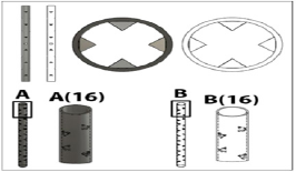
Figure 2: Hollow coaptation device design.
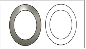
Figure 3: Eight-pronged coaptation device design.
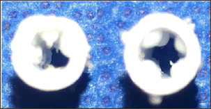
The devices were printed using a Monoprice Maker Ultimate 3D Printer and were manufactured out of 100% fill PLA plastic (Figure 4) . The miniscule scale of the devices pushed the boundaries of how small and precise the printing could be. Devices of each design which most closely matched its corresponding computer model were utilized for each test. All devices tested were 3cm in length with an internal diameter of 4mm, allowing for a snug fit the subject's vagus nerve within the tube. The dimensions of the device can be easily scaled up or down for future studies using nerves of various diameters. Due to the manufacturing limitations with the printer, we decided to modify some of the hollow tubes into our original design, using a Black & Decker rotary tool with a SM Tungsten carbide burr accessory. This was placed cardinally on the outer surface of the tube, separated by 1mm in a 30 degree angle, allowing us to recreate the barbs from our original design (Figure 5) . The resulting oblique pathway of these fenestrations towards the lumen facilitates the placement of the nerve in one end of the device, but anchoring it when is pulled apart (Figure 6).
Figure 4: A. Printed Hollow device. B. Printed Eight-pronged device.
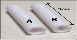
Figure 5: Lateral view of the Barbed device after (top) & before modifications (lower).
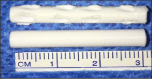
Figure 6: Coronal view of entrance (right) and exit (left) ends of the barbed device. Notice than on the right image the intraluminal projections have a smoother surface and on the left image there’s a spike that will anchor the nerve if pulled apart.
Vagus nerves were harvested from recently deceased goat cadavers, which had been used as part of an unrelated training course. The vagus nerve was selected due to its large diameter, length, and accessibility. All animal procedures were performed in accordance with the standards of our institutional animal care and use committee. (IACUC) Due to anatomical variations between contra lateral nerves, we decided to use the cervical portion only of the cranial nerve and approximately 89cm of vagus nerve were retrieved in total. The specimens were preserved in Lactated Ringer's solution and stored at +4°C until tested the following day, approximately 20 hours later.
Figure 7: Suture repaired nerve.
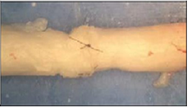
Figure 8: Instron 5542 machine with nerve/device in place.
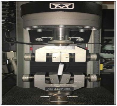
The nerves and devices were tested using an Instron 5542 machine (Figure 7). There were four groups tested: the hollow tube, the ridged tube, sutured and barbed conduit group. The nerves were cut into 4cm segments. 2-0 silk was tied around one end of the nerve and pulled through the device in order to set the nerve in place. Given that the device was 3cm in length, and the nerve segments were 4cm, 1cm of nerve stuck out past the device. The device/nerve combination was placed in the Instron machine with the lower clamp holding the device in place and the upper clamp holding the silk tie connected to the end of the nerve. When the test begins, the machine pulls the silk and nerve upward. The test ends once the nerve is pulled all of the way through the device. All the vagus nerves tested were all approximately the same diameter of 3mm. The sutured nerve group consisted of a 4cm nerve that was severed in half followed by epineurial repair using four cardinal 9-0 nylon sutures to join the stumps back together (Figure 8). The sutured nerve group was tested on the Instron machine by clamping the nerves directly. The test ended when the sutures broke and the ends of the nerve separated. The energy at maximum tensile extension (gf/mm) was measured for each trial, with Instron's Bluehill 2 software package. This value was chosen because it best depicts the resistant force to the separation of the nerve from the device or the sutured nerve.
IBM SPSS Statistics 24 was used to perform all statistical analysis. Independent sample t-tests were performed to compare group sample means. P-values < 0.05 were considered significant.
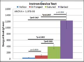
The average energy at maximal tensile extension for the hollow device was 41.23 (±5.00) gf/mm (Figure 9). The eight-pronged device proved to be better at 107.024 (±29.06) gf/mm. While this was more than double the value of the hollow tube, it did not show significance using an independent samples t-test for equality of means (p=0.059). The sutured group produced a result of 392.69 (±66.24) gf/mm, nearly four times the value of the ridged group. But the barbed group outperformed the rest of the cohorts with 1227.36 (250.88) gf/mm. There was a significant difference in the energy at break between both the hollow device and sutured repair (p=0.002) and the ridge and sutured repair groups (p=0.003). These values indicate that the sutured nerve group was significantly more effective at holding the nerve in place that the other conduits, but not better than our proposed device. There was no statistical difference between the barbed and the suture group (p>0.05)
Figure 9: Suture and Barbed are better than Hollow; Suture and Barbed are also better than 8-pronged; and there is no difference between Suture and Barbed.
The incidence of peripheral nerve injury after trauma in the upper and lower extremity is low [7]. but because this could result in such morbidity and disability , and they should be dealt aggressively. These repairs require specialized skills and microsurgical equipment is needed. To introduce a simpler and effective alternative that can save time in the operating room and prevent the use of microsutures is the main drive for this project. For our animal model of nerve repair studies we chose goat vagus nerves due to tissue availability from trauma courses involving said animals [10]. To make microsurgery compatible devices, we used a Monoprice Maker Ultimate Printer was capable on recreating the devices on a larger scale. Modifications were made to our hollow conduit to resemble the original prototype. The caprine and canine vagus nerve were large enough for a device could be fabricated accurately. The hypothesis for the experiment was that the barbed nerve conduit would show greater resistance to separation compared to the hollow or ridge tube and similar to improved resistance to the sutured group. Theoretically, the barbed tube is able to resist the separation of the nerve from the device because the barbs would anchor to the nerve in place and align the fascicles to assist in axonal regeneration. In fact, the breaking point of the nerve with barbed device would not be only limited by the grip that the barbs provide, but also by the strength of the epineurium itself. The model not only will act as a conduit, but also will also hold strongly the severed ends together as sutured. Our hypothesis was supported by the data, by evidencing how much energy was needed to remove the nerve from the device and how there was no different to the neurorrhaphy group. Further testing need to be done with bigger samples to decrease a type I error when we rejecting our null hypothesis.
The proposed design also revealed another fantastic advantage besides conjoining the injured neurite. Having this barbed inward projection will consequently produce outer surface fenestrations that can also facilitate placement of stem cells [11].or regeneration promoting factors like Polyethylene Glycol (PEG) [2]. Platelet Rich Plasma (PRP) or Fibroblast Growth Factor (FGF) [11]. Another aspect to put in consideration is the materials that were used to create the test devices which would not normally be considered for clinical usage. Our conduit needs to be thin, biocompatible and capable produce some inflammatory reaction, but not rejected. It also has to persist and avoid degradation until regeneration has been mostly completed. Partnering with industry facilities should facilitate access to these biological substrates. Alternatively, we focus of our efforts in creating a device that could be engineered and could serve as segmental nerve repair conduit with “built in" suture- less repair mechanisms, decreasing recipient disadvantages of using autologous grafts. Complications such as neuromas, scarring and loss of function will be assessed further using prototype animal models [11]. Future aims of this project could include testing the use of this device in combination with autografts, allografts, or other established conduits. Paprottka et al meta-analysis showed that regardless of the technique used in repairing sensory digital nerve, recovery was 42% and excellent recovery 25% [12]. If including our device into the repertoire of nerve synthesis we can improve this statistics, not only our study will be fulfilled, this will also translate into more productive and satisfied patients.
Our purpose barbed device provided superior coaptation strength compared to standard treatment modalities ex vivo. With additional testing, our design could be advanced to help to simplify and standardize the delivery of an effective nerve repair in a more efficient fashion.


