info@biomedres.us
+1 (502) 904-2126
One Westbrook Corporate Center, Suite 300, Westchester, IL 60154, USA
Site Map

Received: March 07, 2018; Published: March 21, 2018
*Corresponding author: Amy Throckmorton, Associate Professor, School of Biomedical Engineering, Science and Health Systems Drexel University, 3141 Chestnut Street, Rm. 718, Philadelphia
DOI: 10.26717/BJSTR.2018.03.000880
Background: During heart failure-induced lymphedema, the volume transfer from the lymphatic system through the thoracic duct into the cardiovascular system becomes increasingly reduced due, in part, to the high back pressure in the venous system. No minimally invasive devices currently exist that could boost the rate of volume transfer as a long-term means to alleviate lymphatic congestion in decompensated heart failure. To address this unmet clinical need, we are developing a miniature roller pump that is the size of a pacemaker as an implantable device to treat lymphedema. The lymphatic pump is designed for periodic unloading and intermittent volume rates of up to 0.8 L/min and a pressure generation of 20-30 mmHg.
Methods: In this study, we established the initial design of the device per engineering and clinical principles, constructed an initial prototype of the device using acrylic materials, and experimentally tested its performance using a lymph analog fluid in a hydraulic flow loop.
Results: The prototype generated 1-69 mmHg of pressure rise for flow rates between 0.1-1.1 L/min at 400-600 RPM, meeting design requirements. The next phase of optimization will focus on improving pump performance, achieving additional size reduction, and designing the power supply system.
Conclusion: The results of the study support the continued development of this new implantable device to alleviate lymphatic congestion, and thus ease the debilitating symptoms of congestive heart failure in pediatric patients with dysfunctional single ventricle physiology.
Keywords: Mechanical circulatory assistance; Circulatory support; Rotary blood pump; Blood pump; Lymphatic circulation; Roller pump
Abbreviations: CHD: Congenital Heart Disease; TCPC: Total Cavo-Pulmonary Connection; CHF: Congenital Heart Failure; MEMS: Micro ElectroMechanical Systems; CAD: Computer Aided Design; RPM: Revolutions Per Minute
In the U.S., approximately 1 million babies are born with a cardiac defect in need of corrective treatment. Of this cohort, 40,000 live births each year with congenital heart disease (CHD) require surgical interventions [1,2]. In severe cases, babies are born with multiple malformations of their heart chambers and vasculature or single ventricle physiology. The incidence of children born with single functional ventricle is approximately 2-4 per 10,000 births. The treatment of such significant cardiac anomalies is a considerable challenge for clinical teams caring for the patients with CHD [3,4]. In patients with single ventricle physiology, oxygenated and deoxygenated blood mix in the SV, which is a leathal combination? As a treatment approach, the concept of a total right ventricular bypass, first introduced by Fontan and Baudet in 1971 [3], is a palliative surgical procedure aimed at separating the systemic and pulmonary circulations, thus eliminating venous blood mixing.
The current procedure creates the total cavopulmonary connection (TCPC). To compensate for the underdeveloped pulmonary circulation, which leads to high pulmonary vascular resistance and low lung volume, the TCPC is implemented in 3 surgical stages, progressively separating the systemic and pulmonary circulations and gradually increasing blood flow to the lungs. The Fontan completion (3rd stage) produces a configuration in which the single functional ventricle pumps blood through the systemic circulation and then further through the pulmonary vascular beds. The single ventricle experiences a lower preload pressure and a subsequent increase in venous pressure to compensate for the lack of a pressure boost typically provided by a right ventricle. This altered physiologic state is known as the "Fontan paradox.” It has been postulated that late morbidity is related to these higher systemic venous pressures, especially in the inferior systemic veins. The higher the vascular resistance downstream of the liver, the higher the pressure difference required to achieve a given cardiac output.
Thus, the absence ofthis right ventricle in Fontan patients places significant limitations on the amount of energy available to draw and drive blood through the pulmonary vascular beds. Modifications to the original Fontan procedure, coupled with better management, have improved surgical outcomes reducing post-operative mortality to the level of simpler CHD repairs [5,6]. However, Fontan patients are subject to numerous long-term complications, such as venous insufficiency, lymphedema, thromboemboli, arrhythmias, protein losing Enteropathy, to name a few [4,5]. These patients live with a compromised circulatory system and can develop late stage pathophysiology in the months and years after the Fontan operation with decomposition to congestive heart failure (CHF) with 10- year survival rates of approximately 70% [5]. For years, surgical optimization of the TCPC has been the focus of clinicians seeking to streamline vessel connections and to minimize energy losses. Advances in pharmacologic or novel surgical treatments have reached a plateau, resulting in the need for alternative therapeutic options for these patients. A heart transplant is a treatment option, if they can be medically stabilized and survive the organ waiting period.
There is now a growing interest in the use of mechanical circulatory assist devices or blood pumps. By introducing a pressure boost (1-5 mmHg) to the pulmonary circulation analogous to the native right ventricular function, the deleterious characteristics of the Fontan palliation could be reversed to more normal physiologic levels [6]. Although mechanical circulatory devices have been shown to mitigate the failing Fontan physiology prior to heart transplantation, current research indicates device success as only a short term bridge-to- transplant, not for use over an extended period of time [6,7]. Additionally, these devices generally require an invasive procedure for implementation, and no clinically available device has been developed to specifically augment the unique circulatory demands of a dysfunctional Fontan physiology Cavopulmonary assist devices are currently under development, but all are far from reaching clinical use [6]. Thus, there continues to be an unmet clinical need to develop new medical devices as a treatment for CHF in Fontan patients, and the development of a novel method or device to unload the lymphatic circulation would greatly aid in the fluid volume management of Fontan patients with CHF.
Currently, lymphedema-based treatments are primarily palliative and include external compression, pharmacologic strategies, and massage therapy [8]. There has been demonstrated success of lymphedema reversal through cannulation of the thoracic duct, redirecting lymph flow into the cardiovascular system. However, no minimally-invasive medical devices exist that could actively facilitate this volume transfer as a long-term means to alleviate lymph congestion [9]. To address this need, we propose to develop a roller pump as a compact, implantable device to actively treat severe lymphedema in Fontan patients. This type of pump utilizes rollers to compress and propel fluid forward against a pressure gradient. In the proposed application, lymph fluid is displaced from the thoracic duct and ejected into the flow of the subclavian vein. Unlike axial or centrifugal blood pumps, the roller pump design has several advantages:
a) The rollers do not come into direct contact with blood or the lymph fluid;
b) There is limited surface contact with the lymph fluid or blood that could result in cell damage or trigger the coagulation cascade;
c) The wheel-like shape of the roller pump greatly simplifies the motor drive system that will be required for the clinical prototype; and
d) The roller pump geometry will enable the device to be compact and leverage micro electromechanical systems (MEMS) technology.
This device is designed to overcome the unfavorable pressure gradient and drive lymph fluid from the thoracic duct to the subclavian vein. To achieve this, a pump design has been developed, in accordance with physiological requirements, to produce a desired lymph fluid flow rate and venous 'back' pressure of 20-30 mmHg [10]. The goal of this device is to restore the lymphatic circulation in patients to normal levels, and thus to ease the debilitating symptoms of lymphedema in Fontan patients.
The compact roller pump is being developed for positioning in the thoracic cavity to directly connect from the thoracic duct to the subclavian vein, as demonstrated in Figure 1. The pump will operate intermittently to drive lymph fluid when its accumulation requires such action. A roller pump has three crucial defining characteristics: boot angle, roller count, and occlusion gap. The boot angle is the angular distance the tubing travels about a circle after entering and before exiting the pump, the roller count is the number of rollers on the rotating element, and the occlusion gap is the shortest distance between tubing walls when the tube is maximally compressed by a roller. The pump is designed with a 90 degree boot angle and four rollers to favor physiological geometry, minimize cell contact time and shear stress, and minimize flow pulsatility [11]. Tubing diameter was 6mm, constrained by disease state thoracic duct diameter. The flow rate, so as not to impose damage to the subclavian vein, cannot exceed 0.8 L/min of flow [10].
Figure 1: Design concept for lymphatic assist pump. A roller pump will propel fluid from the thoracic duct to subclavian vein. The design includes check valves at inlet and outlet of the pump. In future, the system will be powered by an external controller and battery.

Mathematical modeling enabled us to determine the required pressure generation. We employed the General Energy Equation to characterize the pressure rise that must be provided by the pump to overcome
a) The diseased-state venous "back" pressure and
b) internal pressure losses of the pump system, according to Equation 1:
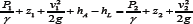
where P1 is the pressure in the thoracic duct, P2 is the subclavian vein pressure, v1 and v2 are the fluid velocities at the inlet and outlet, respectively, z1 and z2 are the heights of the inlet and outlet, respectively, and hL is the head loss as a result of both the fluid flow through the pipe and the drop over the inlet and outlet valves [12]. The internal losses are inherent to flow properties, the resistance of tubing, height difference between inlet and outlet, and the characteristic pressure loss of the required inlet and outlet valves of the system. We acceptably assumed the volumetric flow rate and tube cross-sectional area as constant, and solved for hA. To quantify the expected loss of pressure due to fluid friction of the tubing wall (hL-Darcy), Darcy- Weisbach equations for head loss were utilized. The pressure loss of inlet and outlet one-way valves (hL-valve) in the implantable pump system was determined based on valve geometry. We selected needle valves and estimated the pressure using flow coefficient and orifice design equations [12]. The total head loss (hL-total) for the system was used as hL in calculation of hA of the pump, and is the sum of the pressure drop over the inlet and outlet valves (hL-valve), and the Darcy-Weisbach head loss (hL- Darcy).
Computer aided design (CAD) modeling of the pump geometry was performed in Solid Works and shown in Figure 2a, with a 90 degree boot angle and four roller set up. The apparatus included 3 main components: the motor mount (machined acrylic), pump housing (laser-cut, layered acrylic), and base (machined aluminum). Tracks in the aluminum base enabled precise translation of the housing to set the desired occlusion gap. The screw mechanism on the base front plate allowed for this adjustment, and elastic bands were used to connect the pulley posts to provide supportive tension.
A modular flow loop using an analog lymph fluid was utilized to evaluate the new roller pump prototype (flow loop diagram shown in (Figures 2b&3). The analog fluid had properties of lymphatic fluid density of 1020 kg/m3 and viscosity of 1.6 cP. Tygon tubing was connected to the inlet tank, threaded through the roller pump, and connected to the outlet tank. On the back side, the two tanks were connected with Tygon tubing with a flow probe and clamp that allowed flow rate regulation. The drive shaft of the roller pump was powered by a variable speed drill, and rotational speed was confirmed with a laser tachometer. The flow rate of the fluid was recorded using an ultrasonic flow probe (Model 16PXL, Transonic Systems Inc., and Ithaca, NY). The pressure rise across the pump prototype was recorded using a Validyne differential pressure transducer (Validyne Engineering, Inc., North Ridge, CA) that measured the static pressure in each of the reservoir tanks.
The experimental measurements were acquired using an A/D board and recorded to a desktop computer for post-processing. The data collection process was performed at 50Hz, sampling over 10,000 data points for each operation condition that was evaluated. Each data point corresponded to a pressure rise (mmHg), flow rate (L/min), occlusion gap, and rotational speed that was measured in revolutions per minute (RPM). These data were plotted for each RPM and occlusion gap, and then compared to the target design objectives. Rotational speeds of 400-600 RPM were tested in 50 RPM increments, at three occlusion gaps (input) of 0 mm, 0.5mm, and 1.0 mm. With each RPM and occlusion gap setting, the flow rate (input) was adjusted to represent the desired testing range (0.1-1.1 L/min, increments of 0.1 L/min).
Figure 2: (a) Prototypic testing apparatus built and utilized in verification testing (b) Modular closed flow loop diagram depicting the arrangement of the flow meter, pressure transducer, and the pressurized tanks.

Figure 3: Hydraulic Flow Loop with Instruments and Equipment. A) Tektronic Oscilloscope; B) Data signal conditioner; C) Transonic flow meter; D) Power supply; E) MicroMo brushless DC motor; F) Drive shaft; G) Inlet reservoir tank; H) Pump prototype; I) Validyne differential pressure transducer; J) Outlet reservoir tank; K) Ultrasonic flow probe; L) Flow resistance clamp; and M) Motor and controller.

When considering the estimated head loss in the system and physiological requirements, the required pressure rise, hA, was calculated to be approximately 22 mmHg. Due to variations in diseased-state parameters between patients, it was estimated that the lymphatic pump must deliver between 20 mmHg and 30 mmHg.
The zero occlusion case at all RPMs had the highest maximum pressure generations and maximum flow rates, generating a pressure rise of 1.6-69 mmHg with flow rates of 0.1-1.1 L/min at rotational speeds of 400-600 RPM. At 0.5 mm occlusion, the performance shifted to a pressure rise of 1-30 mmHg with flow rates of 0.1-0.5 L/min at rotational speeds of 400-600 RPM. At 1.0 mm occlusion, the performance further decreased to a pressure rise of 1.3-20 mmHg with flow rates of 0.1-0.4 L/min at rotational speeds of 400-600 RPM. Figure 4a demonstrates flow behavior at three occlusion gaps for one rotational speed, 550 RPM, demonstrating the influence of occlusion gap on pressure rise. With increasing RPM, maximum flow rate and pressure generation increased, as shown in Figure 4b. With zero occlusion, all rotational speeds were capable of generating pressures and flows within the defined performance criteria. With larger occlusion gaps, higher rotational speeds would be required to achieve the criteria.
Figure 4: (a) Pressure vs Flow Rate data for 550 RPM case. With increasing occlusion gap, pressure generation and flow behavior decrease non-linearly, (b) Pressure vs Flow Rate data for all RPMs from 400-600 at zero occlusion gap.

In decompensated CHF, the lymphatic system is overloaded due to fluid retention, has a reduced cardiovascular return against the high venous 'back' pressure, and experiences an increased transfer of fluid into the interstitium. The removal of excess fluid directly from the interstitium through lymphatic drainage has potential to provide immediate functional and symptomatic relief [9]. In clinical studies, treatment of volume overload in heart failure and cirrhotic patients by thoracic duct drainage has been demonstrated to be effective in a small number of patients. Witte et al. [9,14-16] employed a 2 mm Teflon catheter in the distal thoracic duct after it was dissected. The measured lymph flow rate in these clinical cases was between 3-11 mL/min, and total lymph drainage was reported to be between 12 and 44 liters. Signs of lymphatic and circulatory congestion, dyspnea, and orthopnea were significantly diminished. No complications due to the large lymph volume removal were observed. The surgical implementation of this draining approach is complex and could damage nearby critical blood vessel structures.
Thus, we propose to address this unmet clinical need by developing a new medical device. The miniature lymphatic pump will act periodically or continually to unload the lymphatic circulation in CHF patients. This minimally invasive intervention will restore circulatory status by pumping lymphatic fluid from the thoracic duct to the venous circulation via the subclavian vein, thereby actively addressing the cause of lymphedema and potentially reversing the symptoms of CHF. The results of this study indicate that the current proposed roller pump design is capable of performing within the desired performance ranges as a lymphatic pump, as previously defined by physiological constraints and our mathematical modeling, to achieve pressures of 20-30 mmHg and flows less than 0.8 L/min. These data demonstrate the influence of both the occlusion gap and the rotational speed on pump performance. With increasing occlusion gap, flow and pressure generation of the pump decreased. This decreasing trend was expected; as the occlusion gap increases, the pump is no longer propelling the entire volume within the tubing.
As the gap became larger, pressure-flow graphs shifted nonlinearly towards the origin, as seen in Figure 4a, demonstrating the complexity of the occlusion gap's influence on flow behavior. Increasing the rotational speed increases the pressure and flow generation of the pump, as can be seen in Figure 4b. The data presented are representative of pump performance at discrete testing parameters. Occlusion gap and rotational speed can be optimized to desired performance criteria for patient-specific needs.
This study has several limitations. From a clinical perspective, it is expected that cardiovascular stents may be necessary to support the lymph vessel structure during implantation and connection of the device. We are in the process of working with cardiothoracic surgeons to ascertain an optimal implementation and delivery strategy for this device. We also recognize that the lymphatic vessel structure is extremely compliant and that stent reinforcement might be required in order to deploy such a device into the lymphatic circulation. To improve the performance and patient specificity, it is necessary to further characterize the influence of the occlusion gap on flow behavior and on the level of stress to which the lymphatic cells are subjected. There is a general relationship with roller pumps between occlusion gap size and the resultant maximum shear stress: the larger the gap, the lower the shear [11]. Zero occlusion was tested as a baseline performance, and the two gaps tested, 0.5 mm and 1.0 mm, were both wider than the typical 0.250.35 mm clearance seen in cardiovascular continuous flow pumps.
A smaller gap increases stress experienced by the lymph cells, though too large of a gap may introduce flow stasis. While the cellular composition of lymphatic fluid differs from blood, the behavior of its platelet population must be further characterized [14]. Computational fluid dynamics modeling of this behavior may be necessary to characterize the influence of the occlusion gap on flow patterns and cell stresses. In addition, necessary improvements in the testing apparatus were identified; small vibration of the pump housing was noted during testing that introduced variance in the occlusion gap measurement. Further development of this device requires a more detailed understanding of the physiological limitations characterizing this interface between the lymphatic and systemic circulations, such as required flow rates for proper unloading lymph fluid, and maximum shear tolerance of lymphatic cells. This proof of concept prototype showed success in achieving the test criteria, though for clinical relevance, must be scaled down to micro fluidic dimensions, and the drive system must be developed.
This study presents the design, manufacturing, and preliminary performance of the proposed lymphatic roller pump that is designed to relieve the symptoms of CHF-induced lymphedema in patients having dysfunctional or failing single ventricle physiology. The design of the pump took into consideration physiological geometry, flow, and cell stress constraints, and mathematical modeling allowed for characterization of performance criteria. Through experimental hydraulic testing, we achieved pump performance within our target criteria of 20- 30 mmHg pressure rise with flows of less than 0.8 L/min. across the range of testing conducted; the pump is able to perform within the range of 1-69 mmHg pressure raises with flows of 0.1-1.1 L/min at rotational speeds of 400-600 RPM. Our next steps include further design improvement and size reduction in conjunction with the development of the power system to progress toward translational success.
The authors wish to acknowledge the financial support as provided by the Philadelphia-TriUniversity Consortium "Dream Team” Award, for Innovation in Pediatric Research. This is a consortium of Drexel University, the Children's Hospital of Philadelphia, and Hebrew University in Jerusalem. The hydraulic system and pump test apparatus were designed and manufactured with assistance from the Drexel University Machine Shop. The authors have no relevant disclosures, nor conflicts of interest.