 Research Article


Abstract
Background: Aseptic loosening is the major cause of revisions for hip replacement. This mode of failure is often caused by stress shielding. Stress shielding in the femur occurs when some of the loads are taken by the prosthesis and shielded from going to the bone. There is little information regarding the stress shielding among cemented hip implants.
Purpose: The purpose of this study is to investigate the effect of stress shielding on the proximal femur with a femoral prosthesis.
Methods: A patient had undergone open reduction and internal fixation (ORIF) due to a comminuted reversed oblique fracture of the right intertrochanteric hip. ORIF had failed and was converted to bipolar hemiarthroplasty. CT scans were performed on both the right and left hips. Housefield units were determined by using the probe tool. By using equations formulated by Carter and Hays, Linde et al., various parameters such as apparent density, Young’s’ modulus and ultimate strength were calculated. The results were compared to that a native hip.
Results: The hip with the cemented implant had a significant increase in the apparent density, Young’s modulus and ultimate strength, when compared to the left hip. In addition, it was found that the right hip had a higher strain energy density than that of the left.
Interpretation: It has been concluded the most stress shielding occurred in the calcar region of the femur. The instances of stress shielding have been extensively reported for non-cemented or direct bone to implant constructs, this paper reports stress shielding in cemented implants supported by imaging data and biomechanical calculations carried out at the bone-cement-metal interface.
Keywords: Hip Arthroplasty; Hip Implant; Cement Loosening; Stress Shielding
Introduction
Total hip arthroplasty (THA) is often the gold standard for treatment in patients who have arthritic hip joints. There are approximately 231,000 THA which have been performed in the United States, and the incidence has been increasing yearly [1]. The success of these devices is dependent upon bone quality, weight, and activity level [2]. However, THA does have some complications including aseptic loosening, stress shielding, and peri-prosthetic fracture. Bone resorption that occurs as a result of aseptic loosening can often arise from mismatch in material properties between the implant and native femoral bone [3]. Hip implants are generally made of titanium-based alloys, cobalt-chromium alloys, and 316L stainless steel which have greater stiffness values than that of bone. When a metal implant is implanted into the femur, the physiological loading is often transferred to the implant from the surrounding bone. Therefore, the implanted femur is experiencing decreased loads when compared to when it is in its natural state. Bone remodeling occurs in which bone gets resorbed and loses mass, which is known as stress shielding [4]. The reduced bone stock can lead to serious complications including peri-prosthetic fracture, and clinically can present with thigh pain [5]. In addition, stress shielding can also reduce the quality of the remaining bone stock which lead to an increased risk for fracture and aseptic loosening. There has been an increased incidence of revision THAs due to patients who are undergoing THA at a younger age, and increased life expectancy.
Another important complication of artificial hip implants is bone failure, which is often due to increased stress at the contact point between bone and implant. The implant can act as an indentor through a mechanism of interfacial motion of the implant. Therefore, the bone displaces from the implant which causes microcracks in the bone [6,7]. Over the course of several million cycles, those microcracks accumulates and result in failure of bone. In a recent study shows that the failure of bone occurs at the femoral neck, which is the weakest part of the bone [8]. In this study, there was a linear relationship between maximum stress and the number of cycles, that concluded that Maximum stresses decreases as the number of cycles increases.
Materials and Methods
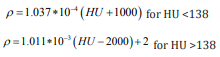
A 67-year-old white female underwent an open reduction and internal fixation (ORIF) due to a comminuted reversed oblique fracture of the left intertrochanteric hip. The ORIF subsequently failed and a conversion to a bipolar hemiarthroplasty was performed. Radiograph of left hip Hemiarthroplasty shows evidence of loosening at the bone cement interface (Figure 1). Increased cortical density is seen in the portion of the femur containing the endoprosthesis. Heterotopic ossification is seen in the proximal femoral region with no extension across the joint. CT scans were performed on the right and left hip. Slices 91-118 had focused on the proximal femur, neck, trochanter and intertrochanteric regions. For comparison slices from both hips were measured. To be congruent with the results same number of slices were measured for both the hips. The Hounsfield units (HU) were obtained using the probe tool. The CT scans had used calibrated images to provide necessary information to define a linear equation which would convert intensity of an image in HU to its apparent density (ρ) in gm/cm3 (equation 1a). For larger HU values, another linear equation was defined (equation 1b) [9].
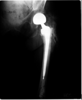
Figure 1: X-ray of the left hip with cemented hemiarthroplasty.
Equation 1&2: Calculate density of bone from Hounsfield Units
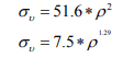
The elastic modulus was calculated based on density-modulus equations, which have been well studied in literature [10-16]. Each of these equations are presented in Table 1. The most frequently used study which investigated the effect of bone composition on bone mechanics which concluded that the stiffness and strength is dependent upon the cube and square respectively of the density [10]. In more recent studies, it was found that the density-modulus equation developed by Austman [16] can better approximate the material properties of ulna [17]. The study by Carter and et al, have used various specimens of bone densities to empirically derive expressions which can be used to estimate the ultimate strength of bone. By using a strain rate of 1% per sec, determination of ultimate strength was determined (equation 3a) [10]. In a recent study, it was found that the strain rate has no effect on the strength. Therefore, in this study the ultimate strength can be determined as seen in equation 3b [18].
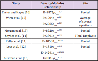
Table 1: Demographic Characteristics of Participants.
Abbreviations: MMSE: Mini-Mental Status Examination; HDS: Hamilton Depression Scale; SANS: Scale for Assessment of Negative Symptoms; SAPS: Scale for Assessment of Positive Symptoms
Equation 3:
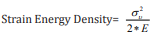
Strain energy density is often derived to being strain energy per unit of volume [9]. Such strain energy density relates to the ultimate strength of a material and young’s modulus (equation 4) [19].
Equation 4:
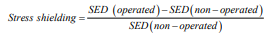
Previous work has shown that stress shielding was quantified based on stress differences in the implanted femur with the intact femur. Using finite element analysis, it was found that stress shielding from the difference in the stress for each element in the bone before and after THA and divided by stresses in the intact bone [2]. In another study, stress shielding has been defined as the change in strain energy density in the implanted bone relative to reference value in the intact bone, as seen in Equation 5 [20].
Equation 5:
Discussion
This is the first study which investigated the effect of hip arthroplasty on the material properties of bone. This retrospective study of a cemented hip arthroplasty developed a method for determining stress shielding. The naïve hip has been used as a comparison, was the key feature for this analysis. It was found that left hip had significantly reduced material properties (i.e. bone density, Young’s modulus, Ultimate strength and Strain Energy Density) when compared with the right hip (p-value=0.0001) (Figure 2). Bone density in the right hip had ranged from 0.3 to 1.5 g/cm3 , which is consistent with density of normal bone [21]. However, the density in the left hip was around 0.11 g/cm3 which does suggest an increased risk for bone fractures [22]. A possible reason for the decreased density in the left hip can be secondary to bone remodeling because of the hip arthroplasty. A possible limitation can be that it is not known about patient duration of the device.
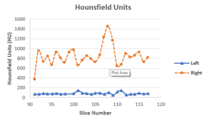
Figure 2: Comparison of the hounsfield units of bone in the right and left hip.
Average Young’s modulus was found to be 6.5 GPa and 0.32 GPa in the right and left hip respectively, which was statistically significant (p-value=0.001). Previous studies have concluded a non-linear model which investigates the relationship between mechanical properties and apparent density [10]. In this study, a linear relationship between Young’s modulus and apparent density was observed (Figure 3). Similar relationship between ultimate strength and apparent density was also observed (Figure 4). In both cases, these linear relationships showed a very strong correlation with r>0.98, which is comparable to study by Linde in 1991 [23]. Compared to the study by Linde [23], this study had analyzed using a 67 year old living female. Whereas in the latter study, it utlized a cadaveric bone. Our study can provide a much more realistic representation.
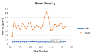
Figure 3: Comparison of density between right and left hip.
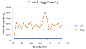
Figure 4: Comparison of the Stress Energy Density between right and left hip.
The average Strain Energy density found in this study was 0.002 N/m2 and 0.00032 N/m2 for the right and left hip respectively, (p-value=0.0001). The higher values of Strain energy density often correspond to bone overload caused by the implant [24]. In addition, the higher strains can be a mechanical stimulus for the bone in which it requires the bone to remodel and strengthen as required. In the right hip, the peak Strain energy density had also corresponded with peak values in both density and Hounsfield Units, which was also concluded in a similar study [24]. This can further explain the correlation that higher strain energy density values will have increased bone resorption.
(Figure 4) represents the stress shielding in the hip as a result of the hip. The negative value represents a stimulus for bone resorption [25]. In this study, stress shielding had occurred throughout the stem of the implant. The lowest value was observed at around slice number 109 which corresponded with the highest value in right hip for Strain Energy density, Bone density and Hounsfield units. The largest stress shielding had occurred in the proximal part of the femur, which does further support previous studies. This study had concluded that the left hip which had the implant was significantly weaker than the right hip (Figure 5). The patient demographics in terms of the duration that the implant was inside her leg is not known. Therefore, it is unclear in terms on when these bone changes were taken place. Stress shielding is one of the instigators for bone loss. Bone loss can be defined as the difference between the operated and non-operated sides. It can be quantified based on the bone mineral content and bone mineral density with the use of DEXA radiographic scans. In this study, we had used CT scans of a patient who had cemented hip arthroplasty. Another limitation was the small sample size. Unlike in previous studies, we had found a linear relationship between density and material properties, with a correlation of 0.98 and greater. This methodology can be quite useful in being able to provide with additional diagnostic tools to possibly prevent aseptic loosening (Figure 6).
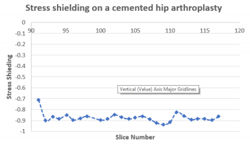
Figure 5: Stress shielding with respect to slice number.

Figure 6: Linear relationship between Youngs’ modulus and Density.
Conclusion
It was found that implanted hip has 86%, 95%, 92%, and 88% decrease when compared to intact hip for density, Young’s modulus, Ultimate strength, and Strain Energy density, respectively. Stress shielding was observed throughout the stem of the implant. Strong linear relationships have been determined between material properties and density (Figure 7).
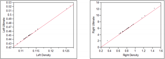
Figure 7: Linear relationship between Ultimate Strength and Density
References
- Kremers HM, Larson DR, Crowson CS, Kremers WK, Washington RE, et al. (2015) Prevalence of total hip and knee replacement in the United States. The Journal of bone and joint surgery. American volume 97(17): 1386-1397.
- Joshi MG, Advani SG, Miller F, Santare MH (2000) Analysis of a femoral hip prosthesis designed to reduce stress shielding. Journal of biomechanics 33(12): 1655-1662.
- Glassman AH, Bobyn JD, Tanzer M (2006) New femoral designs: do they influence stress shielding?. Clinical Orthopaedics and Related Research 453: 64-74.
- Sumner DR (2015) Long-term implant fixation and stress-shielding in total hip replacement. Journal of biomechanics 48(5): 797-800.
- Engh CA, Young AM, Engh CA, Hopper RH (2003) Clinical consequences of stress shielding after porous-coated total hip arthroplasty. Clinical Orthopaedics and Related Research 417: 157-163.
- Elliott B, Goswami T (2012) Implant material properties and their role in micromotion and failure in total hip arthroplasty. International Journal of Mechanics and Materials in Design 8(1):1-7.
- Gunn E, Gundapaneni D, Goswami T (2012) Effect of cement fill ratio in loosening of hip implants. Biomatter 2(2): 87-93.
- Hamandi F, Goswami T (2017) Macrodamage Accumulation Model for a Human Femur. Applied bionics and biomechanics.
- Perillo Marcone A, TaylorM (2007) Effect of varus/valgus malalignment on bone strains in the proximal tibia after TKR: an explicit finite element study. Journal of biomechanical engineering 129(1): 1-11.
- Carter DR, Washington S (1977) The compressive behavior of bone as a two-phase porous structure. J Bone and Joint Surg 59(7): 954-962.
- Keller TS (1994) Predicting the compressive mechanical behavior of bone. Journal of biomechanics 27(9): 1159-1168.
- Lotz JC, Gerhart TN, Hayes WC (1990) Mechanical properties of trabecular bone from the proximal femur: a quantitative CT study. Journal of computer assisted tomography 14(1): 107-114.
- Morgan EF, Bayraktar HH, Keaveny TM (2003) Trabecular bone modulus–density relationships depend on anatomic site. Journal of biomechanics 36(7): 897-904.
- Snyder SM, Schneider E (1991) Estimation of mechanical properties of cortical bone by computed tomography. Journal of Orthopaedic Research 9(3): 422-431.
- Wirtz DC, Schiffers N, Pandorf T, Radermacher K, Weichert D et al. (2000) Critical evaluation of known bone material properties to realize anisotropic FE-simulation of the proximal femur. Journal of biomechanics 33(10): 1325-1330.
- Austman R, Milner JS, Holdsworth DW, Dunning CE (2008) The effect of the density–modulus relationship selected to apply material properties in a finite element model of long bone. Journal of biomechanics 41(15): 3171-3176.
- Neuert MA, Austman, RL, Dunning, CE (2013) The comparison of density-elastic modulus equations for the distal ulna at multiple forearm positions: a finite element study. Acta of bioengineering and biomechanics 15(3): 37-43.
- Ouyang J, Yang GT, Wu WZ, Zhu QA, Zhong SZ (1997) Biomechanical characteristics of human trabecular bone. Clinical Biomechanics 12(7- 8): 522-524.
- Ross MA Mcnulty, Rubash HE, Clohisy J, Beaule, P DellaValle C (2015) The adult hip: hip arthroplasty surgery. Lippincott Williams & Wilkins.
- Weinans, H, Sumner, DR, Igloria R, Natarajan RN (2000) Sensitivity of periprosthetic stress-shielding to load and the bone density-modulus relationship in subject-specific finite element models. Journal of biomechanics 33(7): 809-817.
- Kopperdahl DL, Aspelund T, Hoffmann PF, Sigurdsson S, Siggeirsdottir K, et al. (2014) Assessment of incident spine and hip fractures in women and men using finite element analysis of CT scans. Journal of Bone and Mineral Research 29(3): 570-580.
- Ott SM, Oleksik A, Lu Y, Harper K, Lips P (2002) Bone histomorphometric and biochemical marker results of a 2-year placebo-controlled trial of raloxifene in postmenopausal women. Journal of Bone and Mineral Research 17(2): 341-348.
- Linde F, Nørgaard P, Hvid I, Odgaard A, Søballe K (1991) Mechanical properties of trabecular bone. Dependency on strain rate. J Biomech 24(9): 803-809.
- Epasto G, Foti A, Guglielmino E, Rosa MA (2013) Total hip arthroplasty by using a cementless ultrashort stem: a subject-specific finite element analysis for a young patient clinical case. Proceedings of the Institution of Mechanical Engineers Part H: Journal of Engineering in Medicine 227(7): 757-766.
- Huiskes R, Weinans H, Van Rietbergen B (1992) The relationship between stress shielding and bone resorption around total hip stems and the effects of flexible materials. Clinical orthopaedics and related research 274: 124-134.
