 Mini Review
Abstract
An additively manufactured titanium rehabilitation device was studied, and the existing part was modernized using finite element analysis. Computer Tomography (CT) was utilized for framework design and an implant was developed that perfectly fitted the retrieved bone surface of the patient. Mechanical properties of the implant were studied and checked with finite element analysis. The aim of the study was to reduce the total volume of the titanium implant, thus, to reduce the amount of foreign material implanted into the patient. Finite element analysis was carried out using Ansys software.
Keywords: Dental Implant; Additive Manufacturing; Titanium Alloy; Ti-6Al-4V; Finite Element Analysis
Abbreviations: CT: Computer Tomography; AM: Additive Manufacturing; STL: Stereolithography; LMF: Laser Metal Fusion; STL: Triangulated Surface
Introduction
The first subperiosteal implant was introduced by Dahl in the beginning of the 1940s. It was placed on the jawbone without any fixation. Short description of this procedure: gum tissue was opened and bone surface was revealed to have an impression created. This impression was used to make a gypsum cast that helped design and create the implant framework with precision technologies from a nickel-cobalt-chrome alloy. Afterwards, gum tissue was opened again so the finished frame structure could be fitted to the bone. Then, the wound was closed . Dahl’s method had some disadvantages such as the need of more surgical procedures. Because of this, the method was not used for quite a while [1]. Insertion of dental implants to treat edentulous patients has become a routine procedure over the years [2]. Retention plays an important role when using dental implants. Besides, it is important to mention that implants should not be subjected to high mechanical load [3].
Osseointegration takes place between dental implants and bone tissue, which leads to occlusal loads in the bone. Neighbouring bone tissue around the implant can be highly deformed due to mechanical overload. This case, deformation and stress gradients may exceed biological limits of bone tissue which will lead to micro fractures at the implant-bone interface. Micro fractures can cause implant fracture or bone resorption [4,5]. Invention of CADCAM systems makes pre-surgery design possible, during which a custom-made implant can be created. Design steps of custom-made implants that meet patient-specific requirements are the following: - 2D CT images are converted to 3D DICOM files – use of 3D software for virtual design – 3D Stereolithography (STL) of the implant specimen using 3D printer. [6] During Additive Manufacturing (AM) – or 3D printing in common language – three-dimensional model data is used to create objects with the desired geometry that are built up layer-by-layer [7].
In recent years, numerous studies have been published about the use of additive manufacturing technologies in many fields of medicine [8-11]. The most widespread materials for dental and orthopaedic implants are titanium and titanium alloys, because they can integrate into bone tissue [12-15]. Use of the first titanium implants were documented by Branemark in 1977. Osseointegration after insertion was successful. Titanium and titanium alloys have outstanding biocompatibility, low electric conductivity, good corrosion resistance, and high thermodynamic stability [16]. Behaviour of endosteal implants can be investigated with numeric methods. In recent years, finite element method [17] has been utilized to model peri-implant deformation and stress distribution [18-21], mechanical load direction and magnitude [22,23], and mechanical properties of bone [24,25]. Structural analysis in Finite Element Method (FEM) can define stresses and deformations by considering external forces, loads, pressure, temperature change, and other factors [26].
Materials and Methods
Properties of the Chosen Material
The most widely used titanium alloy for dental implants, prostheses, and other medical devices is Ti-6Al-4V. We used Grade 23 titanium powder for the additive manufacturing of our implants. This material has outstanding corrosion resistance and biocompatibility. LPW Technology Ltd. was the supplier of the metal powder. Table 1 shows the chemical composition of this Ti- 6Al-4V alloy in mass percent.
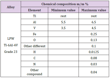
Table 1: Chemical composition of Ti-6Al-4V in mass percent.
Manufacturing
Additive manufacturing was completed with LMF (Laser Metal Fusion) as our generic technology. With additive manufacturing, complex internal geometries can be created, and the workpiece is built up layer-by-layer. Our 3D printer was a Mysint 100 unit, which uses laser beam melting. Printing was partitioned into three major steps: the first was preparation during which three-dimensional models were created and then transformed to STL (Triangulated Surface Data) files. In the second stage, 3D printing was performed before which printing unit parameters were adjusted. The third and last step was post-processing where the specimens were removed from the building platform and their surface was finely machined.
Numeric Analysis of the Custom-Made Titanium Implant
Preparation for Finite Element Analysis
Subperiosteal implant design started with the processing of CBCT images. Figure 1 shows STL files of the patient’s mandibula, which is the lower jawbone. Figure 2 shows STL file of the patient’s maxilla, which is the upper jawbone. Figure 3 shows the result of virtual planning with the maxilla, mandibula, the designed implant, and denture. The final subperiosteal implant was designed based on CBCT images. Mechanical aspects were also considered in the design process of the titanium framework. Figure 4 shows the STL file of our titanium implant design with its three-dimensional geometry that had been analysed with finite element method.
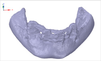
Figure 1: STL file of the mandibula.
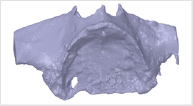
Figure 2: STL file of the maxilla.
Figure 3: Virtual design.
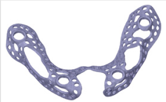
Figure 4: STL file of the designed titanium (subperiosteal) implant.
Results of Finite Element Analysis
Forces had four points of application on the implant, because dentures were connected to those sites. There were 4 parts between the implant and the denture. 3D models of these connecting components and their assembled state is visible in Figure 5 Component no. 1 was a threaded sleeve that was connected to the baseplate with a welded joint. Component no. 2 was the abutment that had a dual threaded connection with a conical part, which contained a hexagonal fitting geometry for assembly. The height of its lateral wall compensated the necessary gum tissue thickness. This surface was the most crucial part of the system, because it provided epithelial tissue adhesion and bacterial isolation between the oral cavity and tissues. Component no. 3 was the bonded interface containing the base for screw fixation to which the crown was fixed. Part no. 4 was a fixing screw with hexagonal connection. Figure 6 shows our tested implant with occlusal forces and fixation support areas. A sleeve was welded into the implant and the abutment was inserted inside. Fix constraints were chosen because the implant could not move on the bone tissue.
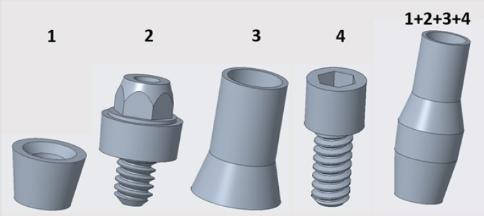
Figure 5: Components used.
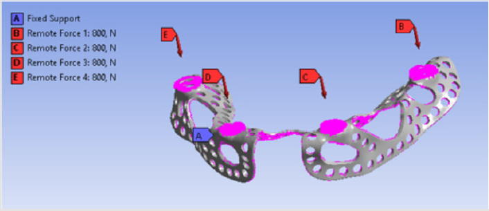
Figure 6: Titanium framework with its constraints and acting forces.
Distant forces were used as they would normally act on the implant from the dental crown. We used data obtained from scientific literature according to which magnitude occlusal forces can be between 100 and 800 N. In the first analysis, maximum 800 N occlusal force was defined. Its result is presented in Figure 7 It is notable that stresses only raised at the acting point of the force. Stress intensity was 287.28 MPa for maximum occlusal load. Another scenario was also investigated in which the frontal part of the implant was loaded with the lowest, while the back of the implant was loaded with the highest occlusal forces. Figure 8 presents the results of this loading scenario with the maximum stress level of 207.6 MPa. It is notable in this case that highest stresses raised at the back of the implant at the acting points of the forces. Different force variations were all analysed from minimum to maximum loads. Figure 9 shows the set of completely linear results. Highest stress intensity was 287.28 MPa for maximum occlusal forces. The studied implant was inserted after manufacturing. Implant fitting to the bone ridge of the patient can be seen in Figure 10.
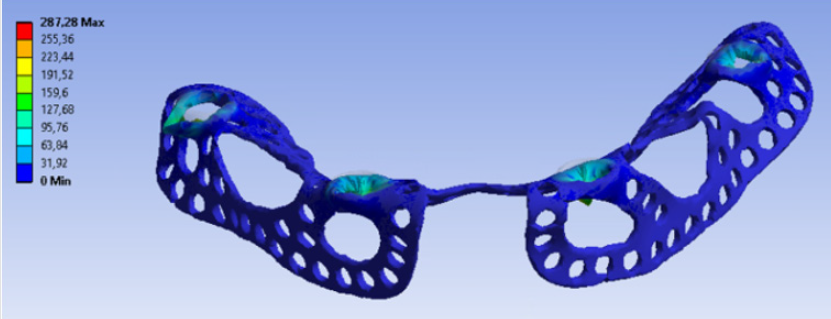
Figure 7: Result from maximum force.
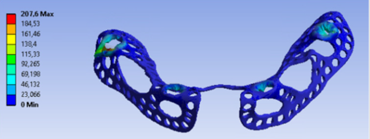
Figure 8: Result from the change in occlusal force.
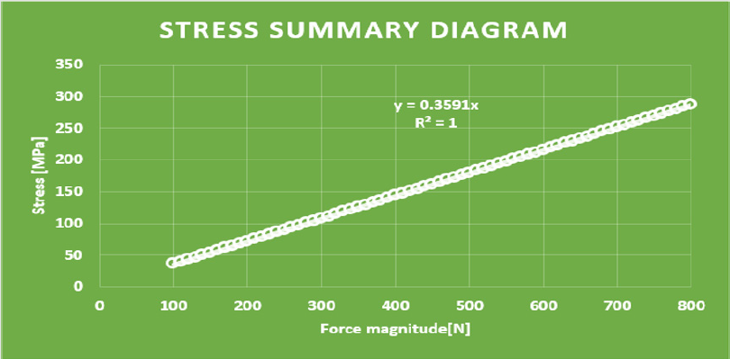
Figure 9: Stress summary diagram.
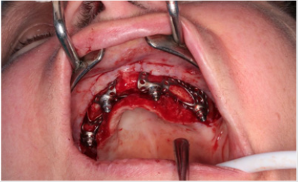
Figure 10: Implant insertion.
Summary
In our mechanical analyses, the highest stress intensity was 278.28 MPa for maximum occlusal load. Yield strength of Grade 23 Ti-6Al-4V alloy is 760MPa, which means if we calculate maximum permissible stress with the safety factor of 2, the structure will still be safe. Volume reduction was successful. Consequently, the mass of implanted titanium alloy was reduced in the patient. Further studies will be conducted to further decrease the amount of titanium material.
Acknowledgement
We would like to express our special thanks to Lajos Bozsányi, a dental technician, CAD and custom-made dental prosthesis designer at Dent-Art-Technik Ltd. “EFOP-3.6.1-16-2016-00017 Internationalization, initiatives to establish a new source of researchers and graduates, and development of knowledge and technological transfer as instruments of intelligent specializations at Szechenyi University”.
References
- Lin GH, Chan HL, Wang HL (2013) The significance of keratinized mucosa on implant health: a systematic review. J Periodontol 84(12): 1755-1767.
- Jingyin L, Shaoxia P, Jing D, Mo Z, Fan Y, et al. (2013) Influence of implant number on the biomechanical behavior of mandibular implant-retained/supported overdentures: A three-dimensional finite element analysis. Journal of dentistry 41(3): 241-249.
- Weinberger LA (1993) The biomechanics of force distribution in implant-supported prostheses. International Journal of Oral and Maxillofacial Implants 8(1): 19-31.
- Gotfredsen K, Berglundh T, Lindhe J (2001) Bone reactions adjacent to titanium implants subjected to static load. A study in the dog (I). Clinical Oral Implants Research 12(1): 1-8.
- Frost HM (1987) Bone “mass” and the “mechanostat”: a proposal. Anatomical Record 219(1): 1-9.
- Rachmiel A, Shilo D, Blanc O, Emodi O (2017) Reconstruction of complex mandibular defects using integrated dental custom-made titanium implants. British Journal of Oral and Maxillofacial Surgery 55(4): 425-427.
- Sing SL, An J, Yeong WY, Wiria F E (2015) Laser and Electron-Beam Powder-Bed Additive Manufacturing of Metallic Implants: A review on process, Materials and Designs. Journal of orthop Res 34(3): 369-385.
- Sudarmadji N,Tan JY, Leong KF, Chua CK, Loh YT (2011) Investigation of the mechanical properties and porosity relationship in selective laser-sintered polyhedral for functionally graded scaffolds. Acta Biomater 7(2): 530-537.
- Yeong WY, Sudarmajdi N, Chua CK, Leong KF, Yu HY, et al. (2009) Porous polycaprolactone scaffold for cardiac tissue engineering fabricated by selective laser sintering. Acta Biomater 6(6): 2028-2034.
- Wiria FE, Leong KF, Chua CK, Liu Y (2007) Poly-ε-caprolactone/hydroxyapatite for tissue engineering scaffold fabrication via selective laser sintering. Acta Biomater 3(1): 1-12.
- Yang SF, Leong KF, Du ZH, Chua CK (2002) The desing of scaffolds for use in tissue engineering. Part II. Rapid prototyping techniques. Tissue Engineering 8(1): 1-11.
- Kim HK, Woo KM, Shon WJ, Ahn JS, Cha S, et al. (2015) Comparison of peri-implant bone formation around injection-molded and machined surface zirconia implants in rabbit tibiae. Dental Materials Journal 34(4): 508-515.
- Van Noort R (1987) Titanium: the implant material of today. Journal of Materials Science 22(11): 3801-3811.
- Rack HJ, Quazi JI (2006) Titanium alloys for biomedical applications. Materials Science and Engineering 26(8): 1269-1277.
- Long M, Rack HJ (1998) Titanium alloys in total joint replacement- a materials science prespective. Biomaterials 19(18): 1621-1639.
- Young Taeg S, Carina BJ, Sarunas P, Krozer A, Jeong Y, et al. (2002) Characteristics of the surface oxides on turned and electrochemically oxidized pure titanium implants up to dielectric breakdown: the oxide thickness, micropore configurations, surface roughness, crystal structure and chemical composition. Biomaterials 23(2): 491-501.
- Geng JP, Tan KB, Liu GR (2001) Application of finite element analysis in implant dentistry: a review of the literature. The journal of Prosthetic Dentistry 85(6): 585-598.
- Rieger MR, Adams WK, Kinzel GL (1990) A finite element survey of eleven endosseous implants. The Journal of prosthetic Dentistry 63(4): 457-465.
- Chun HJ, Cheong JH, Han JH, Heo SJ, Chung JP, et al. (2002) Evaluation of design parameters of osseointegrated dental implants using finite element analysis. Journal of Oral Rehabilitation 29(6): 565-574.
- Himmlová L, Dostálová T, Kácovsky A, Konvicková S (2004) Influence of implant length and diameter on stress distribution: a finite element analysis. The Journal of prosthetic Dentistry 91(1): 20-25.
- Chun HJ, Shin HS, Han CG, Lee SH (2006) Influence of implant abutment type on stress distribution in bone under various loading conditions using finite element analysis. Int. J Oral Maxillofac Implants 21(2): 195-202.
- Meijer HJ, Starmans FJ, Steen WH, Bosman F (1996) Loading conditions of endosseous implants in an edentulous human mandible: a three-dimensional, finite-element study. Journal of Oral Rehabilitation 23(11): 757-763.
- Alkan I, Sertgöz A, Ekici B (2004) Influence of occlusal forces on stress distribution in preloaded dental implant screws. The Journal of Prosthetic Dentistry 91(4): 319-325.
- Kitagawa T, Tanimoto Y, Nemoto K, Aida M (2005) Influence of cortical bone quality on stress distribution in bone around dental implant. Dental Materials Journal 24(2): 219-224.
- Lin CL, Kuo YC, Lin TS (2005) Effects of dental implant length and bone quality on biomechanical responses in bone around implants: a 3D non-linear finite element analysis. Biomedical Engineering: Applications, Basis and Communications 44(17): 44-49.
- Wakabayashi N, Ona M, Suzuki T, Igarashi Y (2008) Nonlinear finite element analyses: Advances and challenges in dental applications. Journal of Dentistry 36(7): 463-471.
