 Research Article
Abstract
Abbreviations: LB: Lip Bumper; FEA: Finite Elements Analysis; CT: Computed Tomography; DLS: Dental Lingual Surfaces; DBS: Dental Buccal Surfaces; RC: Rest Condition; SC: Swallowing Condition
Introduction
The lower Lip Bumper (LB) is a widely employed appliance in the non-extraction treatment of mild dental crowding [1], with stable results in the long-term [2,3]. It is a steel buccal arch running in the oral vestibule between external (lips and cheeks) and internal (tongue) muscles, without contacting any teeth other than first molars. Removing the contractive pressure of lip and cheeks, LB insertion promotes arch expansion under the prevailing lingual pressure, namely a functional expansion effect. Because of the posterior anchorage, molar uprighting, tipping and/or distalization remain mechanical. Most of LB articles describe and quantify the arch perimeter gain [2-18], especially thanks to interdental increases. To this aim, criteria for differentiated LB transverse position from dental buccal surfaces are recommended. More specifically, the LB should be positioned 2 mm away from incisors, 3 mm from canines to 4-5 mm from premolars and molars [1], according to patient tolerance and his perception of aesthetics [1]. Analogously, four vertical levels can be adopted for the LB: coronal (level 1), middle-crown (level 2), gingival (level 3) and sub-gingival, which is the most gingival possible (level 4).
Nevertheless, no corresponding emphasis has been developed on vertical LB models. Our aim was to explore, with a Finite Elements Analysis (FEA), the dental effects produced in the lower arch by varying vertical LB configurations, more specifically 4 vertical levels. Our interest derives from questioning critical effects produced by the LB, which seem to be unavoidable even when inappropriate for treatment, such as incisors buccal inclination [5,8,11,16,18] and molar tipping [4,8-11,15,16,18]. Hence, we first investigated changes occurring in the anterior arch, especially as for incisor inclination. Second, we registered/recorded changes occurring in the posterior arch hypothesizing that the lower the vertical LB position in the vestibule, the more a molar distalizing and intrusion effect is favored.
Materials and Methods
A computed tomography (CT) of a dentate mandible of a 10-year-old child was imported in an image processing software (Mimics 7.10, Materialise, Leuven, Belgium). All teeth were shaped, measured and compared with two dental morphology databases [19-21], registering dental dimensions in terms of mean and standard deviation. Mandibular and dental profile traces were imported in an FEA software (ANSYS 9.0, Ansys Inc. Houston). Solid models were generated from CT traces in the FEA software in 2 steps. First, mandibular bone and dental solid models were developed separately with the same orientation with respect to a common coordinate system (modeling step). Second, they were assembled and a boolean operation was performed to generate the alveolar ridge (Boolean step). The final model consisted of the right mandible hemi-corpus and the corresponding teeth (right lower incisors, canine, first bicuspid, second deciduous molar and first permanent molar, Figure 1).
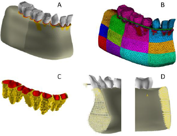
Figure 1:
A) Mandible and dental model.
B) The Finite Element Model (FEM) of the mandible, of lower teeth and lip bumpers. Footnote: Each different colour refers to different mechanical properties.
C) PDL and cortical bone FEM
D) Symmetry constrains applied to the medial aspect of both the mandible model at the symphisis and the LB in the sagittal plane. Constrains along X,Y and Z axes on the distal aspect of the mandibular corpus.
Materials Properties
The cortical bone was considered as an orthotropic linear elastic material with non-uniform thickness and non-constant distribution of mechanical properties [22]. According to the morphological and mechanical characterization reported by Schwartz-Dabney and Dechow [23], the cortical structure was divided into 24 sites (Figure 1), distributed on the buccal and lingual side (BS, LS respectively). Accordingly, cortical thickness, orientation of the maximum stiffness, with respect to the occlusal plane and the values of orthotropic constants, were coupled to each mandibular area (Tables 1A-1C). The spongy bone was considered as an isotropic elastic material 22 and enamel as a linear isotropic material [24] (Table 2). Dentin was considered as a transverse isotropic material [25], whereas the direction of the maximum stiffness is perpendicular to dentinal tubules main axes (Table 2). For the lip bumper material, the properties of stainless steel were applied. The solid model of the periodontal ligament (average thickness 0.25 mm) was meshed using volumetric elements (element size < 0.25 mm).

Table 1A: Cortical bone Thickness and Direction of maximum stiffness values and distribution along the mandibular corpus on both Buccal Side (BS) and Lingual Side (LS).

Table 1B: Cortical bone Orthotropic Young and Shear elastic moduli distribution and values along the mandibular corpus (GPa).
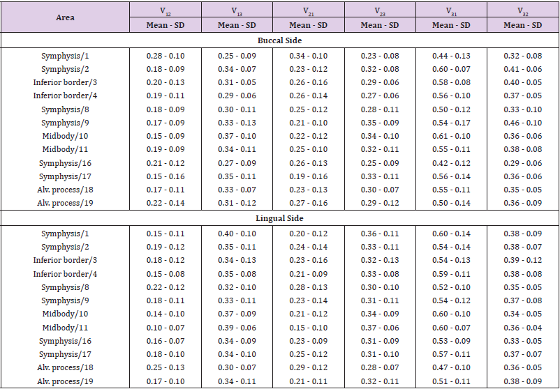
Table 1C: Cortical bone Poisson’s Ratio distribution and values along the mandibular corpus.
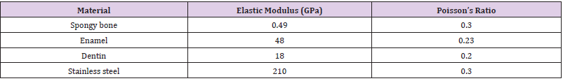
Table 2: Isotropic Material Properties.
A mesh refinement was performed on the internal portion of the alveolar sockets to create a series of 0.7 mm thick element layers simulating the alveolar cortex for each alveolar socket (Figure 1). Available clinical and experimental evidence indicates that the response of the PDL is both elastic and viscous [26-30]. The effect of the non-linear elastic component on the stress-strain curve results in an increased stiffness at higher strain levels. The effect of the non-linear viscous component on PDL stress-strain curves results in an increased stiffness at higher straining rates and a decreased stiffness at lower straining rates. The latter is the case of orthodontic loads with the application of low intensity forces over long periods. The method used to account for the strain-rate dependency of PDL stiffness is based on five stress-strain curves performed at different straining rates [31]. For each of the 5 stress strain curves, an “elastic modulus vs. time” curve was assessed to be implemented in the FEA software. A user-defined sub-routine was set up to enable a time dependent analysis which assessed the strain rate of a given element at each sub-step. The strain value and the corresponding strain rate were interpolated between the “nearest” elastic modulus-time table to evaluate the corresponding stress value according to the following logic flux:
1) n←n+1
2) Increment load and time until load history ends → ΔFn, Δtn
3) k←0
4) k←k+1
5) Solve → 
6) Loop on element “e”
7) Retrive 
8) Modify element Young modulus: 
9) Solve→ 
10) Check equilibrium: 
11) If equilibrium goes to 4, then go to 1.
The PDL stiffness, in a direction parallel to dentine and depending on shear modulus (G), was evaluated through Maceri et al procedure [32].
Tested Models
LB was intended to be made of stainless steel (Table 2). LB was simulated by beam elements with a 1.1 mm section diameter. The distal portion of the LB was connected to the nodes on the buccal aspect of the first molar by rectangular shaped beam elements. Four identical FE models of mandibular corpus were generated, differing only for the type of simulated LB:
A. Model 1: LB located at occlusal dental edges (LB level 1).
B. Model 2: LB located at the middle portion of dental crowns (LB level 2).
C. Model 3: LB located at gingival margins (LB level 3).
D. Model 4: LB located 4 mm apical to gingival margins (LB level 4).
Boundary Conditions
All four mandibular models were constrained along X, Y and Z axes on the distal aspect of the body. Symmetry constrains were applied to the medial aspect of the mandible model at the symphisis and to the medial aspect of the LB in the sagittal plane (Figure 1). Tongue and perioral muscles were simulated by applying pressures on the buccal and lingual aspects of the teeth -dental lingual surfaces (DLS) and dental buccal surfaces (DBS)-. Two conditions were simulated for pressure intensity, namely the Rest Condition (RC) and the Swallowing Condition (SC). Data for pressure intensities in RC and SC were extrapolated in literature for first incisors and first molars both at DBS and DLS [33]. For the remaining teeth, a linear interpolation was derived from first incisor and first molar pressure intensities (Table 3).
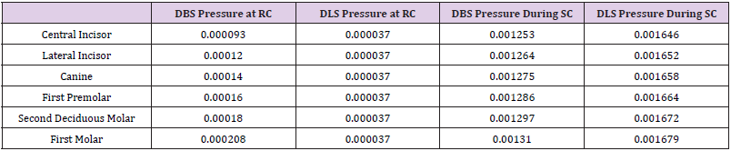
Table 3: Pressures (MPa) applied on DBS and DLS in both RC and SC.
Pressures at RC (Table 3)
Pressures on DLS were equal in intensity and distribution among the mandibular models. Pressures on DBS were distributed according to LB assumption as follows:
A. Model 1 (coronal LB): 50% of lip and cheek pressures at the middle crown and gingival surfaces and 50% at the LB.
B. Model 2 (middle crown LB): 100% of lip and cheek pressures at the LB.
C. Model 3 (gingival LB): 50 % of lip and cheek pressures at the coronal and middle surface, and 50 % at the LB.
D. Model 4 (subgingival LB): 75 % of lip and cheek pressures at coronal, middle and gingival surfaces and 25 % at the LB.
Pressures During SC (Table 3)
Pressures on DLS were equal in intensity and distribution among the models. Pressure distribution on DBS was the same as for the RC condition.
Model Validation
Model validation test in the FE environment consisted in reproducing an experimental test where dental displacements following applied loads were measured in-vivo. To this aim, experimental in-vivo data reported by Cronau, et al. [34] were chosen to validate the current FE model Cronau, et al. [34] measured, in three human subjects, the tip angle of a lower premolar when a couple of forces is applied on the buccal surface of premolar’s crown. These same loading conditions [33] were applied to the premolar of the current FE model. The resulting dental displacement was computed. The tip angle in the sagittal plane was measured as the angle between the premolar main axis in the un-displaced configuration and the premolar long axis in the displaced configuration (Figure 2).
Validation Results
The loading ramp applied in the validation experiments from 0 to 1.5 N/cm produced a tipping movement of the premolar within the alveolar sockets. Figure 2 shows the tipping movement of the premolar amplified with a scaling factor of 200. The relation between the applied torque and the resulting tipping is non-linear (Figure 3). A force amplitude ranging from 0 to 0.5 N/cm produced greater dental displacements when compared with forces ranging from 0.5 to 1.5 N/cm. Ideally, the results of a particular numerical analysis should be validated by alternative experimental methods.
Experimental measurements can be used as part of an integrated approach where dental displacement is measured on a discrete part of a system (i.e., the lower dental arch) identified for a detailed study by a full field numerical analysis technique such as FEA. If possible, results of in-vivo measurements of teeth displacements should form a further important part of any validation process. The premolar tipping computed on current FE model showed a nonlinear relation with the applied ramp of force couples. Such nonlinearity is due to the non-linear mechanical properties coupled with the PDL numerical model. The computed displacements were compared with those measured by Cronau, et al. [34] on three subjects in comparable loading conditions (Figure 3). It can be noted that the displacement fields of the current FE model can be considered as comparable with those recorded in-vivo and comprised in the variability range of in-vivo data.
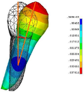
Figure 2: Validation test: premolar tipping resulting from validation conditions.
Footnote: The colour scale reports displacement in mm. The magnification factor for tipping is of 200x.
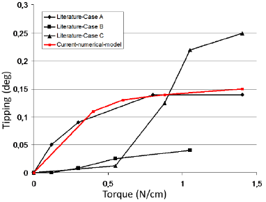
Figure 3: Validation test: premolar tipping resulting from validation conditions.
Footnote: The colour scale reports displacement in mm. The magnification factor for tipping is of 200x.
Results
Model 1- Coronal LB (level 1)
In the RC (Figure 4), incisors, canines and bicuspids moved in the lingual direction. During swallowing (Figure 4), they slightly returned towards the buccal direction. In the RC the rotation center of incisors was located buccal out of the lower third of the root. Incisors tipped lingual and intruded in a combined movement of 0.889e-006. In the SC the rotation center of the incisors was located within the root, between their middle and apical third. A buccal tipping movement of 0.167e-003 was estimated at the edge. In the RC, molars rotated in a distal-lingual direction and tipped distally, with extrusion in the vertical plane. The displacement vectors ranged from 0.1e-004 to 0.6e-004 (Figure 5, Level 1). During SC the same movements became more intensive ranging from 0.233e-003 to 0.544e-003 when measured at the crown (Figure 6, Level 1).

Figure 4: Buccal/lingual inclination of incisor for each Lip Bumper Level both in RC (A-D) and in SC (E-H).
Footnote: Arrows indicates the direction of dental movement within the periodontal ligament. The colour scale indicates the dental movement in mm.
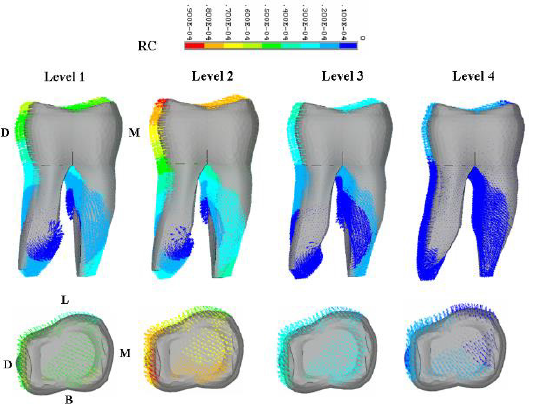
Figure 5: First molar displacement for each Lip Bumper Level in the RC. Sagittal and occlusal view of the molar.
Footnote: Arrows indicate the direction of dental movement within the periodontal ligament. The colour scale indicates the dental movement in mm.
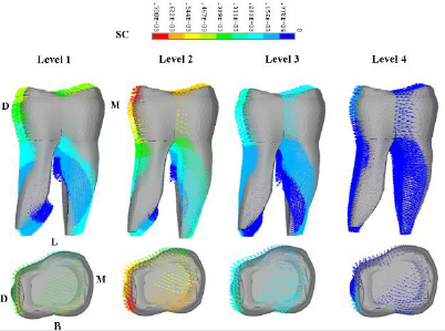
Figure 6: First molar displacement for each Lip Bumper Level in the SC. Sagittal and occlusal view of the molar.
Model 2- Middle Crown LB (level 2)
Incisors, canines and bicuspids moved buccally in both RC and SC (Figures 4), more intensively during function. The rotation center resulted within the incisors, between the middle and apical third of their root. Incisors displacement at the edge was of 0.8e-005 in the RC and of 0.3e-003 in the SC. As for Model 1, molars showed distal-lingual rotation, together with distal tipping and extrusion (Figures 5 & 6). Movement intensity increased with function with a maximum displacement of 0.7e-003 and of 0.9e-004 respectively for the SC and RC.
Model 3- Gingival LB (level 3)
In the RC, incisors, canines and bicuspids moved in the lingual direction (Figure 4). During swallowing, they slightly returned towards the buccal direction (Figure 4). In the RC the incisors tipped (Figure 4), with the rotation center external to the tooth, between the middle and apical third of incisors’ root. In the SC, incisors moved buccally with the rotation centre located within the root between its middle and apical third. The maximum displacement at the incisal edge was of 0.889e-006 in the RC and of 0.167e-003 in the SC. Molars rotated distal-lingual, tipped distal and extruded in both tested conditions (Figures 5 & 6) but with different intensities: 0.3e-004 and of 0.233e-003 respectively in the RC and SC. Both incisor buccal inclination and molar movement during SC were smaller than those estimated with LB level 1 e 2.
Model 4 - Subgingival LB (level 4)
Incisors, canines and bicuspids displacement directions were overlapping those of models 1 and 3 both in the RC and SC (Figure 4). In particular, a more accentuated lingual tipping was found at RC (0.533e-005), while buccal tipping intensity was the lowest found during SC (0.1e-003). Incisor rotation center was located between the middle and apical third of the root, similarly as for model 2. Estimated molar displacement indicated the most irrelevant changes in the vertical, sagittal and transversal planes. The displacement vectors were 0.2e-004 and 0.778e-004 respectively for the RC and SC.
Discussion
The LB is one of the most efficient and versatile non extraction appliance [17] in the non-extraction treatment. LB efficiency is unanimously ascribed to the neuromuscular pattern change, by taking care of a precise transverse LB adaptation from dental buccal surfaces. Deviations from standard LB design are expected to produce different results: LBs 4 mm away from the incisors produce higher forces onto the molars when compared with those registered with a 2 mm position [15]. Also, the adding of buccal shields further increases the arch perimeter gain [9]. While these aspects are usually pondered, the potential of different occlusalgingival levels has not been fully exploited. Besides, incisors buccal inclination [5,8,11,16,18] in already biprotruded malocclusions, undesired molar tipping [4,8-11,15,16,18] and extrusion together with an increased risk for second molar impaction [19] do sometimes question our indication to LB treatment. If versatility of orthodontic tools is developed along different shapes, all possible LB designs should be considered to further increase efficiency.
Along these lines, the aim of our study was to simulate different vertical LB models (coronal, middle crown, gingival and subgingival) and the corresponding dental changes in a bio-faithful environment with FEA. Our analysis was performed separately for active conditions, while the main dental effect resulted from both changes observed in the two tested positions. As expected, this study confirmed the primary LB effect, i.e., the increase of transversal dental diameters for each of the vertical tested levels. Reasonably, the greatest expansion was observed for level 2, because in both tested conditions (rest and function) the lip pressure was kept away from dental buccal surfaces, thus leaving them only under tongue expanding pressure. Since the beginning of orthodontics, incisor position on the mandibular plane is one of the greatest concerns, especially with regard to stability and patient typology. For this reason, in the treatment of already protruded and crowded malocclusions, clinicians complain about the risk of further incisor buccal inclination. Literature data [5,8,11,16,18] ruling out the LB gingival positioning (level 3) as sufficient to avoid this countereffect, are supported in our results.
Incisors buccal inclination took place with level 1, 2 and 3. During swallowing, incisors underwent the same extent of lingual inclination with the lip bumper simulated at level 1 and 3. LB 1 and 3 configurations kept the lip pressure away from respectively the upper 2/3 and the lower 2/3 of the incisors crown. In spite of different vertical LB positioning, incisors underwent similar lingual displacement values in the RC both for model 1 and 3. The reason for this finding can found in the overlapping force distribution on the buccal incisor surfaces and the similar periodontal conditions (i.e., root insertion in the alveolar socket and the crown-root length ratio) hypothesized in our FEA. In model 4, where the lip-incisor relationship was fully kept, a five times higher lingual inclination was estimated when compared with models 1 and 3. On the contrary, the LB positioned at the middle crown of incisors (level 2) interrupted the lip muscle - dental arch contact, leaving the incisors under the sole expanding effect of the tongue. For this reason, even in the resting condition, incisors underwent the expanding force of the tongue with a consequent buccal inclination.
In the swallowing condition (SC), with tongue prevailing over perioral muscles, incisors always underwent buccal inclination. As expected, the tipping effect produced by the tongue resulted more stressed with level 2 LB, in which the counter-balancing lip force was kept away from the incisors. Instead, when the LB application allowed to fully keep the lip-incisor relationship (level 4), lip muscles could contrast the tongue during swallowing. As a result the buccal tipping displacement of the incisors was better controlled. In light of the considerations we have shown up to this point, arch expansion is achieved with buccal tipping of the incisors, if keeping using LB level 1, 2, or 3. Our suggestion when using LB in biprotruded malocclusions is to definitely shift the attention to a more subgingival LB (Level 4), recommended to avoid the worsening of anterior dental protrusion. In presence of crowded arches, treatment efficacy is often inattentively uni-directed on changes in the anterior arch, forgetting that, analogously, changes are occurring in the posterior arch too. At this time, distal tipping rather than bodily distalization, together with molar extrusion, might produce unwanted effects bringing about problems in the vertical dimension or in posterior crowding.
By comparing 260 patients treated with a gingival LB with 135 non treated patients, a recent cephalometric study [19] revealed that treatment enhanced the risk of second molar (M2) impaction by 9 times. Indirectly, the importance of the physical relationship between first (M1) and second molar for a correct M2 eruption35 was stressed, detecting a pre-treatment angulation of M2^M1 > 30° as a risk factor for M2 impactions. The authors explored level 3 LB effects, and suggested level 4 LB as worth considering in future research. Accordingly, we focused our attention on molar displacement, translated into distal tipping for levels 1, 2 and 3 in both loading conditions of our FEA. Molar extrusion was involved in the vertical plane. This occurrence, when not compensated by dento-alveolar growth activation, may jeopardize our treatment in relation to patient typology too. For this reason, this effect has to be taken into account in our non-extraction decision. In contrast with our beliefs, the greatest distal tipping and extrusion were found in model 2 LB rather than in model 1. Even though level 2 LB resulted to be strongly contraindicated in both hyper-divergent patients and in early interventions with M1^M2 > 30° [19], level 1 and 3 LB need to be however monitored throughout treatment.
If the LB is instead positioned very low in the vestibule (level 4), distal tipping does not occur, with a good vertical control. Molar bodily distalization seems possible with a subgingival LB, and this also ensures a correct M1^M2 relationship. In so far, the risk for M2 impaction has not become a further concern of our treatment. Furthermore, a lingual-distal rotation of first molars emerged in the transverse plane. In particular, the rotational effect was prevailing and more marked in the sub-gingival level (Model 4) rather than in other models. This finding reminds us of the importance to slightly expand LB ends if molar contraction is to be avoided. The limitations of the FEA study have to be taken into account. PDL was used to assess dental displacement, but not the subsequent bone remodeling, which can be assumed to be an individual biologic response. Another shortfall of the study was the impossibility of including individual patients behaviour, other interactions and tolerances in the testing conditions”. Taking into account these study limitations, clinical implications can be drawn for individual problem and cost-benefits decisions.
Besides the criteria of a precise transverse adaptation, vertical levels also affect in different ways the extent of space recovery too. Model 2 LB produced the greatest dental expansion both in the transverse and sagittal planes. Hence, this is ideal in resolving severe crowding, with restrictions for protruded malocclusions and labial incompetence cases. The issue of buccal inclination of incisors remains however also with LB levels 1 and 3. The subgingival level appears as the most indicated to avoid this unwanted effect, but on the other hand, it is the less efficient for space gaining in the arch, possibly implying longer treatment time. A careful choice of LB vertical design also affects changes in the distal arch, whereas second molar impactions and vertical dimension increases could delay or even limit our expectations. In so far, because of the prevailing tipping rather than vitalization effect, LB level 1, 2 and 3 employment should be limited to correct under-erupted or mesial tipped molars. The sub-gingival LB might protect from impaction occurrence and vertical extrusion trough a more bodily distal movement. Our FEA confirmed that the gingival level is not sufficient to prevent extrusion, leading us to recommend the subgingival level when the vertical dimension control is a priority. In conclusion, our study highlighted a strong correlation between vertical LB designs and dental changes, describing their countereffects and risks. Hence, a more careful LB choice and use, to include the vertical design together with the transverse, can help in the management of challenging individual malocclusions. In so far, the advantages from varying the level between anterior and lateral bridge should not be overlooked [35].
References
- Cetlin NM, Ten Hoeve A (1983) Nonextraction treatment. J Clin Orthod 17(6): 396-413.
- Solomon MJ, English JD, Magness WB, Mc Kee CJ (2006) Long-term stability of lip bumper therapy followed by fixed appliances. Angle Orthod 76(1): 36-42.
- Ferris T, Alexander RG, Boley J, Buschang PH (2005) Long-term stability of combined rapid palatal expansion-lip bumper therapy followed by full fixed appliances. Am J Orthod Dentofacial Orthop 128(3): 310-325.
- Bjerregaard J, Bundgaard AM, Melsen B (1980) The effect of the mandibular lip bumper and maxillary bite plate on tooth movement, occlusion and space conditions in the lower dental arch. Eur J Orthod 2(4): 257-265.
- Nevant CT, Buschang P, Alexander R, Steffen J (1991) Lip bumper therapy for gaining arch length. Am J Orthod Dentofac Orthop 100(4): 330-336.
- Osborn WS, Nanda RS, Currier GF (1991) Mandibular arch perimeter changes with lip bumper treatment. Am J Orthod Dentofacial Orthop 99(6): 527-532.
- Werner SP, Shivapuja PK, Harris EF (1994) Skeletodental changes in the adolescent accruing from use of the lip bumper. Angle Orthod 64(1): 13-22.
- Davidovitch M, Mc Innis D, Lindauer SJ (1997) The effects of lip bumper therapy in the mixed dentition. Am J Orthod Dentofacial Orthop 111(1): 52-58.
- Hoodge JJ, Nanda RS, Ghosh J, Smith D (1997) Forces produced by lip bumpers on mandibular molars. Am J Orthod Dentofacial Orthop 111(6): 613-622.
- O Donnel S, Nanda RS, Gosh J (1998) Perioral forces and dental changes resulting from mandibular lip bumper treatment. Am J Orthod Dentofac Orthop 113(3): 247-254.
- Ferro F, Monsurrò A, Perillo L (2000) Sagittal and vertical changes after treatment of class II,1 malocclusion according to Cetlin methodology. Am J Orthod Dentofacial Orthop 118: 150-158.
- Murphy Magness WB, English JD, Frazier Bowers SA, Salas AM (2003) A longitudinal study of incremental expansion using a mandibular lip bumper. Angle Orthod 73(4): 396-400.
- Ferro F, Perillo L, Ferro A (2004) Non extraction short-term arch changes. Prog Orthod 5: 18-43.
- Vanarsdall RL Jr, Secchi AG, Chung CH, Katz SH (2004) Mandibular basal structure response to lip bumper treatment in the transverse dimension. Angle Orthod 74(4): 473-479.
- Moin K, Bishara SE (2007) An Evaluation of Buccal Shield Treatment. A Clinical and Cephalometric Study. Angle Orthod 77(1): 57-63.
- Hashish DI, Mostafa YA (2009) Effect of lip bumpers on mandibular arch dimensions. Am J Orthod Dentofacial Orthop 135(1): 106-109.
- Greenfield GL (2010) Non ex factors. 98.5% Nonextraction Therapy using coordinated arch development. (1st Edn) Daehan Narae Publishing, Inc, Seoul Korea, 2: 315-472.
- O Neill J (2009) Do lip bumpers work. Evid Based Dent 10(2): 48-49.
- Ferro F, Funiciello G, Perillo L, Chiodini P (2011) Mandibular lip bumper treatment and second molar eruption disturbances. Am J Orthod Dentofacial Orthop 139(5): 622-627.
- Woelfel JB (1990) Dental anatomy: its relevance to dentistry. Fourth Edition. Philadelphia: Lea and Febiger.
- Kraus BS, Jordan RE, Abramd L (1969) Dental anatomy and occlusion. Baltimore: the Williams and Wilkins Company.
- Nazarian A, Muller R (2004) Time-lapsed microstructural imaging of bone failure behavior. J Biomech 37(1): 55-65.
- Schwartz-Dabney CL, Dechow PC (2003) Variation in Cortical Material Properties Throughout the Human Dentate Mandible. American Journal of Physical Anthropology 120: 252-277.
- Lee JJ, Morris D, Constantino PJ, Lucas PW, Smith TM, et al. (2010) Properties of tooth enamel in great apes. Acta Biomater 6(12): 4560-4565.
- Ryou H, Amin N, Ross A, Eidelman N, Wang DH, et al. (2011) Contributions of microstructure and chemical composition to the mechanical properties of dentine. J Mater Sci Mater Med 22(5):1127-1135.
- Pini M, Zysset P, Botsis J, Contro R (2004) Tensile and compressive behaviour of the bovine periodontal ligament. J Biomech 37: 111-119.
- Decraemer WF, Maes MA, Vanhuyse VJ, Vanpeperstraete P (1980) A non-linear viscoelastic constitutive equation for soft biological tissues, based upon a structural model. J Biomech 1980 13: 559-564.
- Pini M, Wiskott HW, Scherrer SS, Botsis J, Belser UC, et al. (2002) Mechanical characterization of bovine periodontal ligament. J Periodontal Res 37(4): 237-244.
- Shibata T, Botsis J, Bergomi M, Mellal M, Komatsu K, et al. (2006) Mechanical behavior of bovine periodontal ligament under tension-compression cyclic displacements. Eur J Oral Sci 114(1): 74-82.
- Van Driel WD, van Leewen EJ, Von den Hoff JW, Maltha JC, Kuijpers Jagtman AM, et al. (2000) Time–dependent mechanical behaviour of the periodontal ligament. Proc Inst Mech Eng 214(5): 407-504.
- Colin SS, Wiskott HWA, Justiz J, Botsis J, Belser UC, et al. (2005) In vitro time-dependent response of periodontal ligament to mechanical loading. J Appl Physiol 99(6): 2369-2378.
- Maceri F, Martignoni M, Vairo G (2007) Mechanical behaviour of endodontic restorations with multiple prefabricated posts: a finite element approach. J Biomech 40(1): 2386-2398.
- Wenhua Ruan, Min donf Chen, Zhi yuan Gu, Yuan Lu, Ji mei Su, et al. (2005) Muscular forces exerted on the normal dentition. Angle Orthod 75(5): 785-790.
- Cronau M, Ihlow D, Kubein Meesenburg D, Fanghänel J, Dathe H, et al. (2006) Biomechanical features of the periodontium: an experimental pilot study in vivo. Am J Orthod Dentofacial Orthop 129(5): 599.
- Evans R (1988) Incidence of lower second permanent molar impaction. Br J Orthod 15: 199-203.
