info@biomedres.us
+1 (502) 904-2126
One Westbrook Corporate Center, Suite 300, Westchester, IL 60154, USA
Site Map

Received: July 26, 2022; Published: August 09, 2022
*Corresponding author: Ali A H Karah Bash, Department of Electrical and Electronics Engineering, Gaziantep University, 27310 Gaziantep, Turkey
DOI: 10.26717/BJSTR.2022.45.007225
In the conventional treatment method, the ends of the cleft lip are tightened with the medical bandage to minimize the opening area of the cleft lip, using the direct pressure created by the tensile strength of the cleft lip. The traditional method does not provide the ability to control the amount of tension and pressure caused by the pulling of the medical bandage. In addition, the child’s cheek swells owing to the pasting and removal of the bandage several times during the day. Therefore, a new correction method is developed to perform pre-surgical treatment of cleft lip in children. This method is durable, flexible, and easy for a child with a cleft lip. The method has a mechanical part and an electronic part. The mechanical part is made of both leather and plastic, which are suitable for human use. The electronic part consists of electronic components and a control unit. The proposed method is used to reduce the size of the lip incision, improve the formation of the gums, and return the lips and gums to their natural position. The findings show that the proposed method can be used in cleft lip treatment as an alternative to the conventional method. Also, the results showed that the proposed method works efficiently and effectively in the treatment.
Keywords: Cleft Lip; MCU; Sensors; Pre-Surgical Treatment; Mechanical and Electronic Components; Pressure; Airbag
Cleft lip and palate are the most common congenital malformations worldwide. According to international studies, one in 700 babies is born with a cleft lip, cleft palate, or both [1,2]. In uncivilized countries, the child with cleft lip and/or palate leads a very unhappy life if the plastic surgery is not performed in a reasonable time, in addition to the lack of social support and various medical specialties such as (orthodontist, speech therapist, and esthetic surgeons) that deal with the patient cases and perform the necessary medical interventions [3-7]. Some parents prefer to repair their children’s cleft lip only for esthetic reasons, neglecting the age of the child and disregarding the necessary parameters to correct a cleft palate or nasal deformity due to lack of knowledge, poverty, and transportation problems [4]. The cleft may exist on the lip, in the hard or soft palate, in the hard and soft palate, or less commonly on the facial structure [8,9]. Clefts may be classified as complete or incomplete and may also be unilateral or bilateral [10,11]. Furthermore, all oral fissures can be classified for lip and palate clefts. Isolated clefts in the palate are less common compared to other types of clefts. Genetic mutations and environmental factors are among the most significant causes of congenital deformities that affect the fetus during the early stages of its development [12,13]. In addition, alcohol consumption and smoking may have a significant impact on the occurrence of the fissure. Although genes play an essential role in cleft facial development, this is not the only cause of these congenital anomalies [14,15].
When cleft repairs are done early in children with cleft lips and palate, happy and natural life is possible. When cleft repairs are postponed to a later age, children are affected psychologically and socially, especially in terms of self-perception, peer relationships, and physical appearance [16,17]. Researchers [18-20] used several corrective devices to perform pre-correction before plastic surgery, some of which were placed inside the mouth and others as bands outside the mouth. These rubber bands are attached to the cheeks to create some external forces that contribute to the process of alveolar reshaping. In this article, we present a method of treating cleft lip before surgery. It is different from the traditional method because it consists of mechanical and electronic parts that work together during the treatment. The presented method contains control modules, uses pressure and tension. The amount of pressure can be controlled according to the user’s preference, and this feature is not available in the traditional method. The rest of this paper is focused on the following. In the materials and methods section, the method used in this study is described in detail. In the result and discussion section, all experimental results obtained during this research are presented. Also, the findings are discussing and explaining in detail. As for the last section, it included the conclusions.
Our research protocol was reconsidered and approved by the scientific board of Gaziantep University (Number: E-28313576- 300-4516). In this paper, the mechanical and electronic parts of the procedure are explained. Before designing the mechanical frames of the method, the typical sizes of a child’s head from birth to three months of age were retrieved from a previous study, as listed in (Table 1) [21-23]. According to previous studies, the baby’s head is measured around the largest area of the head starts from the top of the eyebrows toward the back of the head. An inelastic band is used for measuring the circumference of the child’s head. The measurement starts from the front area over the eyebrows to the most prominent point at the back of the head. The measurement is repeated thrice then the highest value is recorded. According to the previous study, the measurement of the child’s head circumference is usually done on the first day after birth [22].
Figure 1:
(A) Right side of all frames of the mechanical part together.
(B) Back side of all frames of the mechanical part together.
(C) 3D view of mechanical part frames.

Figure 2: 3D section of front frame.

Table 1. Sizes of a child’s head at different ages.

In this section, we will explain the mechanical part of the method. The mechanical part is divided into some frames, the first frame as shown in (Figure 1a) is the head frame. This frame is primary part which looks like a hat that is placed on the baby’s head. It is also the main irreplaceable frame that connects all the frames of the method. The Lateral frame is the second support frame, connected to the hat on one side and face down on the other. This frame holds the front of the device and connects it to the front of the face. It is also flexible and portable as shown in (Figure 1a). It also holds the front part in its proper position, which should be at the upper lip of the mouth. So, it is an important element and indispensable. The back frame shown in (Figure 1a) is considered as a supporting frame, which is located behind the child’s ear. It also represents a link between two previous mentioned frames. Another frame is the front frame, which is considered the most important frame of the method, as shown in (Figure 1a & Figure 2). It connects to the head frame and covers the upper lip of the mouth. It is used to return the cleft lip to its natural position and to reduce the opened area of the cleft lip by tightening the edges of the lip and applying direct pressure to the upper lip area. Where it is possible to take advantage of the flexibility of the cartilaginous septum in the first weeks of the birth of the baby with a cleft lip (due to the high levels of hyaluronic acid found in infants) [11].
This frame has an electronic pressure and temperature sensors. Pressure sensor uses to electronically measure the amount of pressure applied to the cleft lip. The amount of pressure varies from a child to another according to his situation. (Figure 1b) shows the mechanical frames connected together from the back side. (Figure 1c) also displays the mechanical frames in form of a three-dimensional (3D) side image. The pressure is supplied using the airbag as shown in (Figure 2), which will be located in the front frame at the location explained by the red rectangle in the (Figure 2). The length of it is 3.7 cm, the height is 1.346 cm, and thickness is 2 mm. Also, it takes arc shape at the upper, and be rectangular from the lower.
In this paper, MCU manufactured by Microchip is used because it is easily programmed and with up to (8K X 14 words) of flash memory technology allows up to a thousand re-writes. Furthermore, it has speed and low consumption properties in many uses, such as remote sensors and safety devices. It has a 10-bit Analog to Digital Converters (ADC) channel, (256X8 bytes) EEPROM, and (8/16-bit) timers, making it an excellent choice for this study. Additionally, the MCU can receive information from the Analog to Digital Converter Circuit (ADC) and process the data. In this paper, the ADC feature of MCU is used for reading the voltage of the existing sensor (pressure sensor) as shown in (Figure 3). the sensor can be calculated through the following transfer functions:
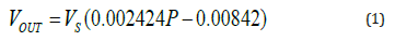
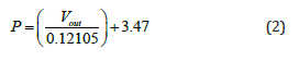
where Vresolution is the voltage resolution of the ADC of MCU. The VOUT is an output voltage of the pressure sensor, VS is the input voltage (≈5V), and P is the pressure value that is measured by the pressure sensor. Also, the timer of MCU is utilized for the time delaying and counting. Besides, MCU has two ports of PWM (C1 and C2) that are employed for controlling the air pump and valve. As for the pressure sensor, it also deals with an analog voltage and responds to changes in pressure. This sensor is used to measure the pressure, which ranges between (20 - 400 Kpa) (150 – 3000 mmHg). The pressure sensor is a modern pressure sensor that provides an accurate, high-level analog output signal proportional to the pressure exerted on the sensor. The power supply is prepared to meet the design specifications. Most of the electronic components work on 5 volts DC. In this study, a power source was designed that provides 5 and 3 volts to run all the study units. A 12-volt DC source was utilized, and by means of a voltage regulator, the voltage was reduced to 5 with 1.5 ampere to suit the system requirements. The voltage regulator is applied to keep the DC voltages level at a constant amount. Also, the study contains two types of motors (air pump and valve). An air pump is used to fill the airbag by a certain amount of air so that it creates pressure on the cleft lip area. This motor operates on (3.3V DC) voltage. As for the valve, it is utilized to empty the airbag from the air, as this motor operates at a continuous voltage of (3.3V), the exhaust velocity is (3 sec), and maximum current is (170 mA).
Figure 3: Pressure sensor (MPXHZ6400A) that is used in this study.

The ADC available in MCU uses a 10-bit register through the analog to the digital conversion process. Thus, the quantization size will be 1024 (Vresolution = 2n), n is a number of bits of ADC. The resolution voltage, the pressure sensor output voltage at each pressure value, and the pressure measured by When the device is turned on, the temperature and pressure values will be displayed on the screen (LCD). The motors in the device can be turned on and off by the switches. Air pump motor can be started to fill the airbag with air, so when the air inside the airbag is an increase, the pressure also will be increased. The pressure amount inside the airbag can be read immediately by the pressure sensor and the result will appear on the LCD. The pressure is employed to return the gum to its natural position because the gum of the child with the cleft lip will be moved forward than the natural position. The pressure will improve the locations of the cleft parts and repair the lip skin and muscles permanently [6]. Whereby the width of the pulse entering the air pump motor coming from the MCU can be changed, which changes the speed of the air pump motor. The technique of PWM is the time during which the pulse is high (duty cycle), that is, the percentage of time during which the component or device is working, which leads to changing the value of the voltage entering the air pump motor. The time cycle and the amount of change in voltages can be calculated by the following equations:
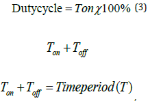
f = 1 is the time on,
𝑇𝑜𝑓𝑓is the time off,
time off, f is the frequency period and 𝑉𝑜𝑢𝑡 is the output voltage of the pressure sensor. Through experiments, it was found that the maximum pressure that the airbag can handle is (500 mmHg), so when the air pressure inside the airbag reaches (500 mmHg), the control unit in the device will stop the air pump motor from pumping air into the airbag as a means of protection for it. The valve is employed to trap and deflate the air inside the airbag. When the valve is operating, it allows the air to pass from the air pump motor towards the airbag. But when it is in the stopped state, it will empty the air inside the airbag. The speed of the air pump motor can be controlled by using the pulse width modulation (PWM) feature available in MCU.
Table 2. Sizes of a child’s head at different ages.

Within experiments, it was determined that the working range of the pressure sensor output voltage ranges from 0.5146 V (345 mm Hg) to 0.764 V (500 mm Hg), as shown in (Figure 4a). It is noted that the voltage values are very close to theoretical calculations using equations (3, 4, and 5). It has also been observed that when operating the air motor using (4V DC), it needs (10 sec) as a period until the pressure reaches the maximum value that the airbag can bear, as in the (Figure 4b). As mentioned earlier, to control the speed of the air pump motor we used PWM (C2 port) technology available in the MCU. We used nine duty cycle values across the range (5.12 %, 100 %). At each duty cycle value, the input voltage value of the air pump motor was calculated as shown in (Table 2). Note that voltage values range from (0 – 5) volts. PWM technology has 8-bit registers, so the maximum value it can reach is 256 (28-bit); hence its working range is (0-255). Through experiments, it was found that the time required to reach the maximum pressure that the airbag can handle without operating the heating system unit is (10 sec). However, when the temperature increases, the pressure will increase, and the time to reach the maximum pressure will decrease, where it will be (5 sec) when temperature is (40.7 °C) and pressure is (500 mmHg) as depicted in (Figure 5).
Figure 4:
(a) Relationship between pressure and voltage.
(b) Relationship between pressure and time.

Figure 5: Shows the relationship between pressure and temperature.

In this work, the mechanical and electronic parts of a new method are proposed. This method can be used instead of the conventional methods in pre- surgical treatments of cleft lips before performing the corrective plastic surgery. The method is very flexible, which makes it easy for children with a cleft lip to wear and remove it several times during the day. This method is employed to return the cleft lip and gum to their natural position and reshape them before the correction surgery using direct pressure. The pressure is employed to restoration the gum to its original position. Also, it improves the locations of the cleft limbs and rehabilitates the muscles. The pressure amount can be controlled by the control unit. This feature is not available in the traditional method. Furthermore, the mechanical part frames can be elongated or shortened, depending on the size of the child’s head. The results showed that in the future, GSM module technology could be added with this procedure so that one could run the procedure from a distance and control all the modules available in it.