 Perspective
Abstract
Artificial Bio-mimetic membranes are perfect tool to examine and display response of molecular transport across mediums of certain concentration. Microfluidic techniques can be employed for fabrication and characterization of artificial membranes. This work comprises the design of a microfluidic lab-on-chip system for fast and programmable artificial bio-mimetic membranes designed by droplet interface bilayer mechanism. The state of the art is the device fabrication methodology, its application and scope of usage for fast, dynamic and repeatable DIB studies.
Keywords: Digital Microfluidics; Droplet-Interface Bilayers; Photolithography
Introduction
Microfluidics [1-4] as an emerging technology of fluid manipulation provides control, flexibility as well as size scaling of large experimental techniques down to handheld Lab-onchip systems. Many types of lab on chip systems are realized since the advent of the technology, in particular the pioneering work of Stephan Quake [2,3] for multiphase flows in microfluidic channels led to the development of state of the art technology called, Droplet microfluidics or Digital/Discrete microfluidics [5- 7]. The generation of highly monodisperse droplets in microfluidic devices, in specific “droplet-makers” geometries, is generally based on a controlled dispersion of an aliquot (dispersed phase) in a continuous fluorocarbon oil (carrier phase). The size and content of droplets can be easily controlled by changing the flow rates of liquid streams prior to droplet formation and the composition of the dispersed phase. Many types of geometries are in use for high throughput production of assays at kHz rates, namely T-junction, co-flow, flow focusing, step emulsification and capillary microfluidics [8-10]. These very systems not only revolutionized the mixing and controlled encapsulation as well as paved the way for industrial scale ultra-high-throughput generation of mono disperesed emulsification for applications like RNA and DNA sequencing [11,12], synthesis of nanoparticles and quantum dots [13,14], hydrogel-encapsulated droplet bilayers [14], synthesis of soft micro-capsules [15] and hydrogel particles [16], 3D droplet bilayers [17], digital PCR [18-20], transport analysis [21,22] and recently organ in droplet [23]. The field has flourished from its development, but also directed an increase in the application and diversification of the experiments, which could be performed on and off chip. Here we present construction and characterization of droplet based soft bilayer, which is often regarded as Droplet- Interface-Bilayer (DIB). The method focuses on mass production of DIB network where a droplet interacts with same species of droplet in a plane while at few selective regions, a particular droplet shares membrane with other type of droplet species (which may or may not be sharing membrane with same species). By this, response of a particular droplet association with other types could be modeled. We see the prospects of this technique to further increase the bulk DIB networks programming. The device constructed had three layers, two layers of PDMS (top and bottom) and a middle layer with on-demand membrane pores with selectable size. (Figure 1a & 1b) present the general idea of a flow focusing geometry for production of mono disperesd microdroplets of size 100μm at generation rate of 2KHz (droplet frequency determined by [8,10]) in square microchannels.
Whereas (Figure 1c & 1d) represents two droplets in spatially separated channels approaching and interacting through a membrane hole/pore (size selected by Laser puncturing technique presented in (Figures 1-7) and finally making a stable droplet based artificial bio-mimetic membrane. Three substrates were fabricated by soft lithography. For simplicity, channel dimensions were kept rectangular and height of 100μm was achieved by spin coating (protocol optimized by need). PDMS replication was performed. First layer was plasma bonded with channel facing upwards, middle layer was aligned and bonded followed by top layer with channel facing the middle layer. Both active channel regions were facing the middle layer. For better device operation and droplet interaction, middle layer needed to be as thin as possible while strong enough to hold the pressure exerted by flow profiles of two drop makers. This middle layer could be of either PDMS or Perylene. Each of the materials used for middle layer had different protocols for constructing. We used a planer perylene sheet of 10μm thickness (special thanks to Prof Bruno le Pioufle SATIE ENS Paris Saclay for providing the processed perylene sheets protocol adapted from [24]), sandwiched between two slabs of PDMS as depicted in (Figure 2). Results of laser induced fluorescence measurement proved the significance of the system to study diffusion and its relation to the size of the interface (DIB).
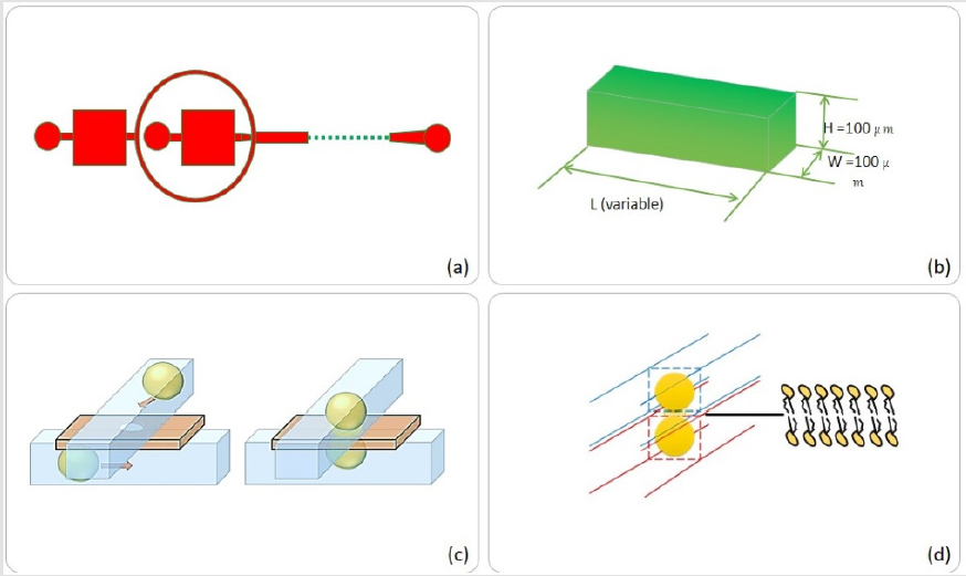
Figure 1: Microfluidic device design steps,
(a) Flow focusing microfluidic system with chamber areas of choice, (b) Chamber/channel dimensions,
(b) Pro- posed action of top-bottom anchoring, (d) Droplet interface bilayer by two interacting droplets.
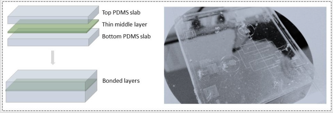
Figure 2: Proposed device model of multilayered microfluidic Droplet Interface Bilayer (DIB) device.
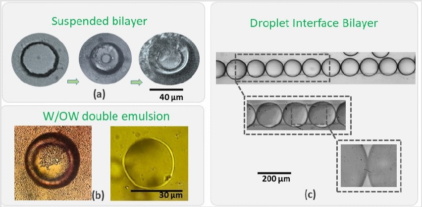
Figure 3: Different methods for artificial soft bio-mimetic membrane fabrication: (a) A suspended open chamber microfluidic system for planer suspended bilayer, (b) W/O/W double emulsion by microfluidic approaches and (c) droplet interface bilayer.
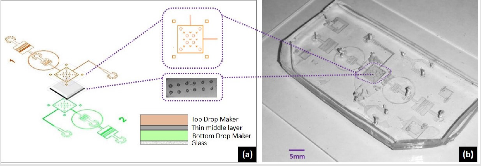
Figure 4: Microfluidic device design steps, (a). Flow focusing microfluidic system with chamber areas of choice, (b). chamber/ channel dimensions, (c). pro- posed action of top-bottom anchoring, (d). droplet interface bilayer by two interacting droplets.
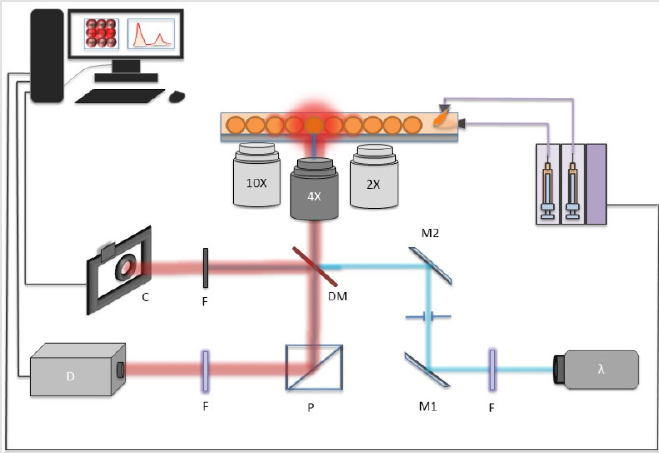
Figure 5: Setup discussed earlier; the laser sources used in the study are highlighted.
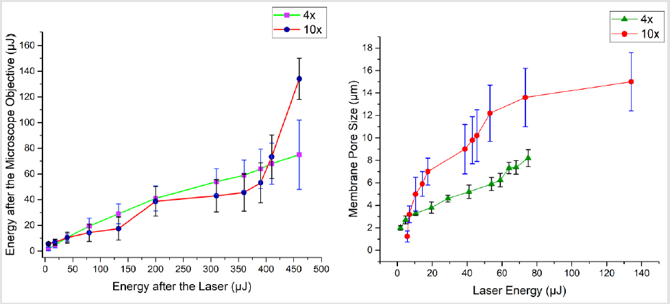
Figure 6: Laser energy and its effect on shape of the perylene pore: (Top) laser energy optimization before and after the microscope objectives (for this study, two microscope objectives were used, a 4x and 10x), (bottom) laser energy and corresponding pore size.
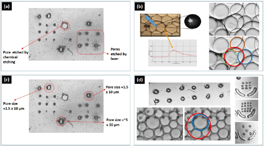
Figure 7: The middle layer and its processing comparison, (a) a Perylene middle layer with a comparison of chemically etch pore of 30μm and laser assisted puncturing, (b) resulting device operation for successful droplet-interface- bilayer formation, (c) optimization of the membrane puncturing mechanism by using liquid coolant, (d) further operational optimization to achieve almost circular puncturing.
Artificial Bio-Mimetic Membranes
Suspended Bilayers
To increase the yield and the repeatability of the soft membranes, we employed a method of droplet interaction. In this study we provide insights of droplet based artificial biomimetic membranes from technology design perspective. We present construction and characterization of droplet based soft bilayer which is often regarded as Droplet-Interface-Bilayer (DIB). Artificial Bio-mimetic membranes are perfect tool to examine and display response of molecular transport across mediums of certain concentration. Various techniques are employed for fabrication and characterization of artificial membranes. The significance of these membranes came from the relevancy in terms of reconstruction of naturally occurring membranes (which often act as barriers). By controlling few parameters, naturally occurring membranes could be re-synthesized in laboratory as well as at industrial scale. As the standards to fabricate these models are known, one can model the functionality of the artificial membrane. Soft membranes could be categorized as suspended bilayer, droplet interface bilayer and unilamellar vesicles when dealing with microfluidics domain.
Last two types concerns droplet microfluidics technology which provides control on size, fractionizing, labeling, incubating, trapping and controlled release. Out of various techniques and methodologies, soft (artificial) bio-mimetic membranes are of much importance to understand the transport mechanism. There are various methods to develop artificial membranes, of which most common are of three major types, suspended bilayer, droplet interface bilayers and W/O/W emulsion. The structure, shape and orientation of artificial soft membranes fabricated by droplet microdfluidics are depicted in (Figure 3). The foremost type is good tool to understand and perform in different conditions, not only the transport mechanism but to stain the suspended bilayer and study the electrical and optical properties of the membrane. Figure 3a shows a typical experiment of a two-chamber multiphase flow, open microfluidic device used for making a suspended lipid bilayer. Experiment were performed by the protocol adapted from Basam et al. [25]. When modified (using a home-built surfactant), the success of such protocol varies rapidly mainly because of the dependence of factors like temperature, atmospheric pressure, device cleanliness, liquid reagents and vibration on the experiment stage.
The suspended bilayer found to be highly fragile and very hard to maintain unless special precautions are met for instance, performing experiment in a chamber with moderate vacuum. The reusability of such open chamber microfluidic systems is not user friendly, which requires harsh cleaning, drying and baking procedure. In terms of droplet microfluidics, the target of a million droplet detection per second [26,27] has already been achieved, in that context, a system for reusability of the experiment discussed earlier, require, on demand bilayer formation and release methodology. The advantages of new droplet-based system over open microfluidic system would be the superiority of the technology to offer discrete micro-environment for quickly making a dropletinterface- bilayer (in few seconds and without tricky procedures).
Droplet Interface Bilayer
Dangla et al. [28] reported that by etching a micro-hole or a micro-grove on top of a microfluidic channel binds the droplet to that hole/groove [28] mainly due to change in the surface energy of the droplet when squeezed in the channel. The droplet is attached to the hole maintaining a balance between its surface energy and interfacial tension. This attachment of the droplet to a hole is termed anchoring. To develop such effect so that two or more droplets are anchored in a system, we proposed systems of multilayer microfluidic platforms which results in successful bottom-up droplet-interface-bilayers of two species of droplets and without any sophisticated surface treatments or atmospheric contamination of the sample. When two or more droplets (in case of two droplets, each droplet with different concentration and different analyte) were subjected to contact, a strong and stable interface is formed between droplets. That interface is termed as DIB (Droplet Interface Bilayer). The advantages of using DIB as membrane transport studies is the stability and reusability of the membrane as compared to suspended lipid bilayers which are fragile and complicated to handle. The approach developed in this study gave a handy solution of DIB between two population of droplets acting as one donor and one acceptor condition.
Design and Microfabrication of Multilayer System
To tackle challenge of programable DIB size, we developed a system of two drops following in two channels (as outlined Figure 1) and interact through a pore. The complete device design included channel dimensions, wettability condition and bonding of different layers. For the work involved in this study, flow focusing geometry was used. The microfabrication was carried out by standard photolithography where first CAD layouts were drawn for 3 4inch rectangular masks followed by transparent sheet printing. A negative photoresist (Su8-2075) was spin coated on 3.5inch Silicon wafer by spin coating equipment followed by soft bake. The photographic mask was loaded to the mask aligner and exposure machine, and for 100μm spin coated thickness, UV exposure at 350nm for 22s crosslinked the exposed region. Hard bake followed by wet etching finalized the mold for replica-molding. After drying, PDMS (Polydimethylsiloxane) in 10: 1 composition was poured on the substrate and baked at 750C for 4hours. The device constructed had three layers, two layers of PDMS (top and bottom) and a middle layer with pore. Three separate substrates were fabricated by soft lithography, two containing drop makers with flow focusing geometry (Figure 1a). and one substrate for middle layer sandwiched between two thick (100μm) PDMS structures. First layer was plasma bonded with channel facing upwards, middle layer was aligned and bonded followed by top layer with channel facing the middle layer. Both active channel regions were facing the middle layer. For better device operation and droplet interaction, middle layer needed to be as thin as possible while strong enough to hold the pressure exerted by flow profiles of two drop makers. This middle layer could be of either PDMS or Parylene. Each of the materials used for middle layer had different protocols for constructing. Best choice for the middle layer was to use PDMS with thickness of 5μm to 20μm. But at this scale PDMS layers need to be spin coated to reach the desired homogenous thickness. After spin coating, PMDS is baked and processed by generic PDMS bonding process. Only issue is, with thin layer of PDMS, the lift-off is very tricky. The prototype testing arose a new challenge of middle layer delamination and optimization of the device construction lead to design the system to a whole new level. We sandwiched the rectangular cut shape parylene by the help of circular mechanical pillars inside and interlocking pillars outside the chamber regions. This gave the advantage of homogenous thickness and smooth lamination of the middle layer. After bonding the three layers, complete device was functionalized for computability of the fluorinated oils. The construction of the device is outlined in the (Figure 4). The middle layer pores were made without chemical etching yet a high-power Nd:Yag laser operating at 355nm was focused tightly at the perylene layer.
Experiment and Results
Laser Assisted Membrane Pores
Laser assisted perylene puncturing is the unique membrane pore crafting strategy, we proposed in the system where the need of 3 to 9 hours of cleanroom occupancy for etching of structured pores was efficiently replaced by a mere 5s laser engraving/puncturing. The setup used in the device design and later fluorescence measurement is depicted in (Figure 5). where a neMESYS Syringe Pumps were used to push the fluids. The interconnect between the syringes and the microfluidic chip were performed by 1mm tubing. An Olympus inverted microscope was set with 516nm Dichoric Mirror (DM). For visual inspection of the laser engraving a monochrome camera with laserband-stop filter was set. Finally, a photo-spectrometer was set to record the fluorescence measurements. With such system, we could select the size and shape of the pore by changing the laser spot size or beam-expander before the microscope stage. Furthermore, to effectively puncture the membrane hole, some precautions needed to be taken, else the shape of the pore will be elliptical or oval. In order to employ the puncturing mechanism, we found that, the certain limitations of the process need to be taken care of, which enlist
a) Laser stabilization for minimum one hour engraving/ puncturing to be performed without attached substrate (essentially, first the device is fabricated with all three layers and then laser puncturing is performed) as it’s a pulse laser, so energy per pulse could differ, so does the resulting pore size, thus shutter speed to be programmed to be highly selective.
b) Use of a XYZ-transitional stage taking precautions while puncturing (use of cooling agent) else it could end up ridges and hanging material debris, enough to clog the channels.
The pore formation was carried out by first filling the two chambers, which are segregated by the porous membrane. In one chamber, we filled the water while in other, we used the coolant. By using commercially available industrial coolant,HFE7500 the excessive heat dissipation by the laser spot was minimized and resulted in almost circular shaped membrane pores. The chamber close to microscope objective needs to have coolant, while the other chamber could be filled with any liquid. As the other chamber needs to have a slight flow of the fluid to avoid the debris aggregation. The resulting shape of membrane pores, without a cooling agent is shown in (Figure 7a & 7b). while with cooling agent (HFE7500) is shown in (Figure 7). By employing such techniques, very fine 1μm to 20μm pore size was achievable. To make bigger pore sizes or other shape of traps, translation stage XY movement could be programmed (beyond the scope of this work. The laser energy and resulting membrane pore sizes are shown in Figure 6.
Delamination Testing
The new system prototype was tested for delamination among layers. This was done by following fluids in crossflow between two chambers. Fluids were flushed by the syringe pumps provided by neMESYS. For top chamber, water was pumped at very high flow rate, 1500μl/h from input side while same flow rate of water was injected from output region of the bottom chamber at once. Due to change in the channel lengths from input to output region, top chamber was filled first, which exerted some pressure on the suspended membrane while from bottom chamber fluid added pressure to compensate the membrane stretching inside the chamber. When both the chambers were filled, the elasticity of PDMS causes the system to swell at chamber regions which could easily push the system to delaminate. The device handled pressure up to 2500μl/h and it caused the delamination. The idea behind this high flow-rate testing was to observe the membrane elastic strength. Flow rates as high as of 7500μl/h, did not cause membrane rupture (further investigation needed to test the maximum pressure to rapture the membrane), thus the system was marginally reliable (flow rates lower than 1000μl/h) for mass transport experiments.
Florescence Measurement at DIB
For the testing of reliability of the idea proposed to anchor and then perform optical inspection of mass transport, we used the setup (Figure 5). for mode of CW 488nm lasers source. In first, droplets of Rhodamine B (2mM in water) were made in Krytox (5μl/25mL in HFE7500) in bottom chamber of device (Figure 4b). while top chamber of the device was filled with water droplets made in Krytox (5μl/25mL in HFE7500). Thus, the bottom droplet acted as donor while upper water droplets acted as acceptor reactor. This way, we were able to study the transport of the dye solution from one drop to another with a droplet interface bilayer with variable sizes (sizes are controlled by the membrane pore size). Experiments were repeated for Fluorescence (2mM in water) solution to study the effect of dye diffusion from one drop to another.
The microfluidic system showed the dye diffusion efficiently, but a question of intra-species transport and diffusion put up a new experimental challenge. As both chambers housed one type of population of droplets, cross talk among one type of droplets is evident provided that the surfactant concentration is not high. Cross-talk among one type of droplets could reduce the system reliability to act as measure of single droplet interface bilayer sensor. A typical result of decay in Rhodamine droplet while a strong crosstalk among neighboring 4 droplets is depicted in (Figure 8). When droplet size is compatible to chamber dimensions, effect of crosstalk is less as compared to smaller droplets as in such case, the change in pressure of poly dispersed droplets could affect increase in size of big droplets and system is somewhat unstable for desired operation of a single droplet interface bilayer sensor. Another case study included, use of two dye loaded drops, subjected to bilayer membrane transport. The experiment data is presented in (Figure 9). The bottom chamber was filled with Fluorescence droplets while top chamber was filled with Rhodamine-B droplets. As both of these dyes, could be excited by 488nm laser, thus an experiment of effect of crosstalk among two species of dye loaded droplets was conducted. Laser was focused at a fixed spot on droplet-interface and fluorescence data was recorded for 30 minutes with one-minute interval. The time laps show a steady increase in rhodamine signal while fluorescein shows slight decline. The purpose of the case study was to study the diffusion of high concentration of one type of dye, from one droplet to another droplet loaded with another type of dye and to probe at the bilayer region, the transport, yet the signal shape shows, possibility of aggregation of dye molecule at the interface is much strong that none of the dyes diffuse into neighboring droplet. But the effect of same species crosstalk is still possible.
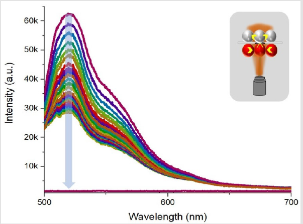
Figure 8: The fluorescence decay in Rhodamine-B drop when irradiated by 488nm laser source and effect of cross talk among same type of droplet population.
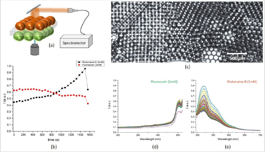
Figure 9: The fluorescence time laps in Rhodamine-B and Fluorescein drops when irradiated by 488nm CW laser source and effect of cross talk among two different type of dye loaded droplets, (a) proposed idea of Rhodamine-B drops on top while Fluorescein drops in bottom chamber, (b) time vs intensity in both drops - when measured at the interface, (c) a multiplier network of hundreds of droplets in two chambers with effective drop size of 80μm, (d) the blue shifted signal decrease in Fluorescein drop and (e) the fluorescence signal rise in Rhodamine-B drop in time.
Conclusion
To increase the yield and the repeatability of the soft membranes, we employed a method of droplet interaction. We provide insights of droplet based artificial bio-mimetic membranes from technology design perspective. We present construction and characterization of droplet based soft bilayer which is often regarded as Droplet- Interface-Bilayer (DIB). A termed coined for contour contact of one drop to another in a reservoir as candidate to produce, maintain, study and release artificial biomimetic membranes (droplet monolayers are region of interaction forming a droplet-interfacebilayer). Various options could be employed, out of which a serial/ planner droplet interface network is of most common (Figure 3c), where sequential droplet membrane network is a proper method for concentration gradient studies. But such kind of approach limits the studies of mass transport while considering two species of droplet contents (Figure 7) without cross contamination. We on the other hand, address the mass transport phenomena in biomimetic droplet bilayers and to account for such requirement, a prospect is to interact two distinct type of droplets, segregated by a mechanical surface with selectable openings. This approach gives control, not just on reusability but effective membrane(droplet interaction region as membrane)size and shape. Moreover, the range of operation in such systems includes, two distinct types of droplets dispersed in same or different types of continuous phase. Further advancements are required to avoid the interspecies droplet diffusion to study and to develop single droplet interfacemembrane sensor.
References
- Gravesen P, Branebjerg J, Jensen OS (1993) Microfluidics-a review. Journal of micromechanics and microengineering 3(4): 168-182.
- Thorsen T, Roberts RW, Arnold FH, Quake SR (2001) Dynamic pattern formation in a vesicle-generating microfluidic device. Phys Rev Lett 86(18): 4163-4166.
- Squires TM, Quake SR (2005) Microfluidics: Fluid physics at the nanoliter scale. Reviews of modern physics 77(6): 977.
- Whitesides GM (2006) The origins and the future of microfluidics. Nature 442(7101): 368.
- Choi SA, Lee S (2019) Encapsulation of streptococcus salivarius in double emulsion droplets as a method for increasing the efficacy of oral topical medications. BJSTR 19(2): 14193-14197.
- YS Kurniawan (2019) Micro total analysis system application for biomedicals-a mini-review. BJSTR 12(4): 9442-9443.
- Pedini P, Kouba N, Riquier M, Simon S, Basire A, et al. (2019) Droplet digital PCR-a new technology for detection and quantification of chimerism after allogenic hematopoietic stem cell transplantation. BJSTR 13(4): 10065-10068.
- El Abed AL, Taly V (2013) Real-time detection and analysis of whispering gallery mode resonance in high-throughput flowing monodisperse micro- droplets. Optical Materials 36(1): 64-68.
- Belloul M, Bartolo JF, Ziraoui B, Coldren F, Taly V, et al. (2013) High-throughput formation and control of monodisperse liquid crystals droplets driven by an alternating current electric field in a microfluidic device. Applied Physics Letters 103(1): 033112.
- Hayat Z, El Abed A (2018) High-throughput optofluidic acquisition of micro- droplets in microfluidic systems. Micromachines 9(4): 183.
- Moon HS, Je K, Min JW, Park D, Han KY, et al. (2018) Inertial-ordering-assisted droplet microfluidics for high-throughput single-cell RNA-sequencing. Lab on a Chip 18(5): 18775-784.
- Pellegrino M, Sciambi A, Treusch S, Durruthy-Durruthy R, Gokhale K, et al. (2018) High-throughput single-cell dna sequencing of acute myeloid leukemia tumors with droplet microfluidics. Genome research 28(9): 1345-1352.
- Abalde-Cela S, Taladriz-Blanco P, Oliveira MG, Abell C (2018) Droplet microfluidics for the highly controlled synthesis of branched gold nanoparticles. Scientific reports 8(1): 2440.
- Baxani DK, Jamieson WD, Barrow DA, Castell OK (2018) An encapsulated droplet interface bilayer array for the high-throughput optical mea- surement of lipid membranes with single bilayer resolution, Biophysical Journal 114(3): 686a.
- Bchellaoui N, Hayat Z, Mami, Dorbez-Sridi R, El Abed (2017) Microfluidic-assisted formation of highly monodisperse and mesoporous silica soft microcapsules. Scientific reports 7(1): 16326.
- Heida T, Neubauer JW, Seuss M, Hauck N, Thiele J, et al. (2017) Me-chanically defined microgels by droplet microfluidics. Macromolecular Chemistry and Physics 218(2): 1600418.
- Hwang WL, Chen M, Cronin B, Holden MA, Bayley H (2008) Asymmetric droplet interface bilayers. Journal of the American Chemical Society 130(18): 5878-5879.
- Millot F, Harrak A, Hutchison JB, Larson JW, Hutchison JB, et al. (2011) Quantitative and sensitive detection of rare mutations using droplet-based microflu- idics. Lab on a chip 11(13): 2156-2166.
- Mollajan M, Bazaz SR, Mehrizi AA (2018) A thoroughgoing design of a rapid-cycle microfluidic droplet-based PCR device to amplify rare DNA strands. Journal of Applied Fluid Mechanics 11(1): 21-29
- Postel M, Roosen A, Laurent-Puig P, Taly T, Wang-Renault (2018) Droplet-based digital PCR and next generation sequencing for monitoring circulating tumor DNA: a cancer diagnostic perspective. Expert review of molecular diagnostics 18(1): 7-17.
- Bai Y, X. He, Liu D, Abell C, Huck WT, et al. (2010) A double droplet trap system for studying mass transport across a droplet-droplet interface. Lab on a chip 10(1): 1281-1285.
- Gruner P, Riechers B, Semin B, Lim J, Johnston A, et al. (2016) Controlling molecular transport in minimal emulsions. Nature communications 7: 10392.
- Chen Q, Utech S, Chen D, Prodanovic R, Lin, et al. (2016) Con- trolled assembly of heterotypic cells in a core-shell scaffold: organ in a droplet. Lab on a Chip 16(8): 1346-1349.
- Le Pioufle, Suzuki H, Tabata KV, Noji H (2008) Takeuchi, Lipid bilayer microarray for parallel recording of transmembrane ion currents. Analyt- ical chemistry 80(1): 328-332.
- Takeuchi S, Mojzisova H, Chauvat D, Zyss J, Suzuki, et al. (2009) Electro-optical imaging microscopy of dye-doped artificial lipidic membranes. Biophysical journal 97(11): 2913-2921.
- Hatch AC, Fisher JS, AR, Yang DL, Lee AP (2011) 1-million droplet array with wide-field fluorescence imaging for digital pcr. Lab on a chip 11(22): 3838-3845.
- Yelleswarapu VR, Jeong HH, Yadavali S, Issadore D (2017) Ultra- high throughput detection (1 million droplets per second) of fluorescent droplets using a cell phone camera and time domain encoded optofluidics. Lab on a Chip 17(6): 1083-1094.
- Dangla R, Lee S, CN Baroud (2011) Trapping microfluidic drops in wells of surface energy. Physical review letters 107(12): 124501.
