 Case Report
Abstract
This article reports the case of a female patient with class III malocclusion due to maxilla retrognathia that was treated with a Hybrid Maxillary Expander. The patient was clinically exanimated, intraoral scanned and sent to CBCT. The laboratory received the scan and the CBCT images and sent the virtual planning of the future location of the mini-implants to the medical team and a 3-dimensional surgical guide was printed. The expander was obtained in the laboratory and sent with the surgical guide to the medical team that soldered the expander and inserted the mini implants under local anesthesia with the aid of the printed surgical guide. The patient was instructed to activate the appliance twice a day under a 90-degree turn until the Hyrax screw reaches the end and remained in situ for 3 months.
Keywords: Class III Malocclusion; Hybrid Hyrax Expander; Virtual Planning; CBCT; Intraoral Scan; Printed Surgical Guide; Orthodontic Mini-Implants
Introduction
In orthodontics, anchorage is of great importance, it can determine the failure or success of the treatment. With the use of mini implants, the orthodontists can benefit of absolute anchorage in their treatment plan. Mini implants for orthodontic anchorage have been used for a while now, and the results didn’t hesitate to come. In addition to the absolute anchorage that TADs are providing, they can also be inserted by the orthodontists’ and not necessarily by an oral surgeon. Although a problem appears when there is not enough space between the adjacent roots for inserting the implant safely, a solution is found in surgical guides [1]. Wrongly inserted mini implants can lead to complications as root hypersensitivity, fracture of the root or of the alveolar bone, damage of the inferior alveolar nerve or maxillary sinus perforation [1]. If it is done, root damage can be mild with the complete healing of the periodontal ligament at the removal of the mini-implant or, with severe damage of the root that will lead to an anchylosed area that will have impact on tooth movement [1]. Besides these complications, during the placement of a TAD blood vessels and nerve injuries might occur. Even though they have a low frequency rate, if surgical guides are not used, in the palatal area of the maxilla injuries of the greater palatal nerve and artery might happen.
Also for the mandible in the retromolar area, retromolar pad and the buccal side of the alveolar bone lesions of the blood vessels and nerves can be done [2]. An advantage in placing mini implants in the palatal vault is besides the great anchorage that they provide in expansion, the risk of root damage in this location is non-existent [3-8]. More frequently, in the surgeons’ office, when treating a patient with implants, besides a very detailed diagnosis and treatment plan, the placement of the implant is very important. Inserting implants is not at all an easy task for the surgeon. Besides the anatomic elements that lie in the maxillofacial region, the existing bone level is also a concern that needs to be fully known before starting the insertion of the implant. The stress of a surgeon when inserting implants it’s at a high level because of the precision and skill that are needed for a proper management of the clinical situation (Figures 1 & 2).

Figure 1: Frontal intraoral view of the occlusion.
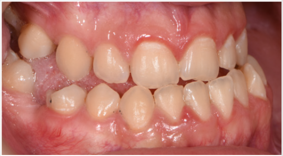
Figure 2: Lateral right intraoral view of the patient’s occlusion.
Materials and Methods
A female patient presented in our office for a consult. Her oral hygiene status needed improvement especially in the frontal upper area. Intraoral photographs reveal that in the transversal plane she had crossbite contacts between all the teeth and severe discrepancy between and the midline of the face the upper arch midline which was deviated to the right with almost the size of a lower incisor. In the sagittal plane she had canine class III on the right side and class I on the left side due to the rotated mandibular left canine and end to end to inverse overjet in the anterior region (Figures 3 & 4) and in the vertical plane, she had 1 to 2 mm of inverse overbite and bilateral open bite. Her upper right maxillary molars were absent and she presented moderate crowding in both upper and lower arch. The steps in the treatment plan were to expand the maxilla with the aid of a Hybrid Maxillary Expander followed by fixed appliances on the both Arches. In this case report, we present the results after the expansion of the maxilla and the processes that needed to be followed for the fabrication of the Hybrid Maxillary Expander. The first steps in the digital planning were clinical examination and intraoral scanning. The patient was referred to a radiological center for a CBCT. The intraoral scan and the CBCT were sent to the laboratory and analyzed for the implant planning. The mini screws were planned to be inserted in the anterior part of the palate, paramedian, this being an optimal area that has lower variability of bone thickness, a thinner mucosal layer and a lower density of blood vessels compared to the other [9].
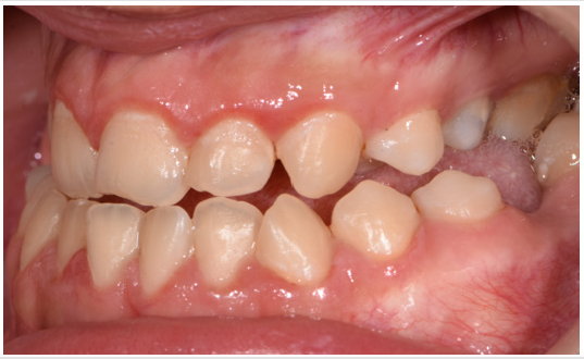
Figure 3: Lateral left intraoral view of the patient’s occlusion.
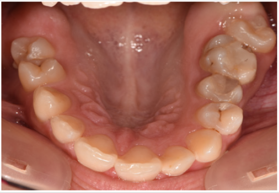
Figure 4: Intraoral view of the upper arch.
The CBCT showed favorable implant planning positions, with more than half of their length fixed in the bone. Although the left side of the vault was not as thick as theright one, a thin blade of cortical bone remained between the nasal cavity and the mini implant on the left side of the patient’s palate (Figures 5 & 6).
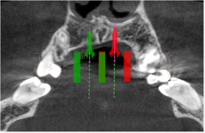
Figure 5: Image of the planned site of the mini implants in transverse section.
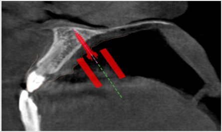
Figure 5a: Virtual planning of the palatal implants insertion. Image of the left mini-implants’ site in sagittal section.
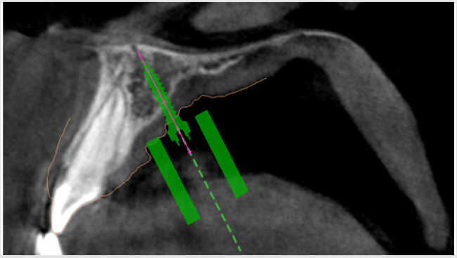
Figure 6: Virtual planning of the palatal implants insertion. Image of the right mini-implant’s site in sagittal section.
The screws were planned to be angled toward the root of the incisor and as perpendicular as possible to the palatal surface for sufficient retention and efficiency [9]. After the acceptance of the digital planning by the medical team, a surgical guide was 3D printed. The Hybrid Maxillary Expander that was sent from the laboratory on a 3D printed cast consisted of two band sone on the second right upper bicuspid and another one on the first left upper molar, a median screw that was linked to the two paramedian mini-implants and two soldered arms that linked the median screw to the bands. The expander was bonded and in the same appointment, the mini implants were put in place using the printed surgical guide under local anesthesia. After the appointment, the patient was trained to activate the appliance twice a day, under a 90 degree turn until the screw reached the end. The patient was also informed about the apparition of a transitory diastema that was the sign that the suture had opened, and the treatment is successful. At the end of the expansion period, the appliance was kept in place for a 3-month period for healing of the mid-palatal suture that will deliver stability and low chance of relapse (Figures 7 & 8).
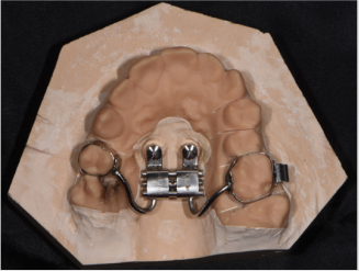
Figure 7: The resulted hybrid expander on the 3D printed model.
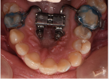
Figure 8: Intraoral photography of the Hybrid Maxillary Expander in place.
Results
At the end of the expansion period, the anterior and posterior crossbite was solved and in the vertical plane, the lateral open bite had clearly improved. The upper jaw from the occlusal view has visible changes in its transversal dimension and space was gained, proof being also the diastemas that appeared between all teeth not only the median one. After the expansion, the patient will wear edgewise appliances for correction of the crowding, the interincisal midlines and for detailing and stabilizing the occlusion (Figures 9-11).
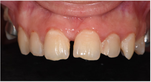
Figure 9: Frontal view of the upper jaw during the expsion therapy. A transitory diastema occurred.
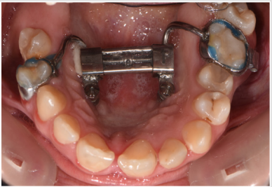
Figure 10: Occlusal view of the upper jaw at the end of the expanding therapy.
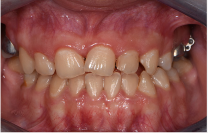
Figure 10: Clinical situation at the end of the expansion therapy.
Discussions
Nowadays, with the technology becoming more and more reliable, the insertion of implants has become a lot easier with the help of surgical guides that have the main objective to direct the drilling system of the implant [4]. CBCT is most commonly used in the orthodontists’ practice for evaluating bone density and height of the palate concerning the insertions of mini implants for the expansion of a narrow maxilla [5,6]. Orthodontic virtual planning is aiding the medical team in diagnosis and accomplishment of a favorable treatment outcome in cases that are not frequently encountered [7,8]. Authors have also been focusing not only on providing surgical guides but also in developing new software for measuring the cephalometric radiography used frequently in the orthodontic field [9]. It is also important to keep in mind that the chemical composition of mini implants can affect the biocompatibility and success of orthodontic anchorage [10]. Class III malocclusion is a frequent encounter in a compressed maxilla and skeletal anchorage does its’ best in expansion. With no tipping of the teeth and an effective action on the mid-palatal suture, the Hybrid Maxillary Expander achieves skeletal expansion. Another advantage of the appliance is that the patient’s cooperation is relatively low, the surgical part being non-invasive and well supported.
Conclusion
Digital planning generates a more precise and efficient method in both implant positioning and fabrication of the appliance. Even though it might seem a difficult intervention, the surgical guide used provides a flapless insertion of the mini-implants that leads to little to no swelling or pain experienced by the patient afterwards.
References
- K Niranjani (2014) Guiding Templates for Mini-Implants in Orthodontics: A Systematic Review. Journal of Dental Sciences.
- Anna Znamirowska Bajowska, Tomasz Ogiński, JaninaSzeląg (2011) Complications During Surgical Insertion of Miniimplants. Dent Med Probl 48(1): 11-18.
- Maino G, Paoletto E, Lombardo L, Siciliani G (2015) MAPA a new high recision 3D method of palatal miniscrew placement.
- Raja Subramonian, Karthik, Rachuri Narendrakumar (2013) Implant surgical guides: From the past to the present. J Pharm Bioallied Sci 5(1): S98-S102.
- Popa A, Szuhanek C, Brad S Accurate Determination for Orthodontic Mini-implant Placement Using Acrylic Resin Surgical Guide and CBCT. Materiale Plastice 53(2): 287-288.
- Szuhanek C, Nagib R, Sinescu C, Negrutiu ML, Manea N, et al. (2018) Orthodontic Mini-Implants Hybrid Expanders in Palatal Expansion. REV CHIM 69(7): 1905-1906.
- Barreto FAM, Santos JRRC (2018) Virtual orthodontic setup in orthodontic camouflage planning for skeletal Class III malocclusion. Dental Press J Orthod 23(2): 75-86.
- İzgi E, Pekiner FN (2019) Comparative Evaluation of Conventional and OnyxCeph™ Dental Software Measurements on Cephalometric Radiography. Turk J Orthod 32(2): 87-95.
- Bjorn Ludwig, Bettina Glasl, S Jay Bowman, Benedict Wilmes, Gero SM (2011) Anatomical Guidelines for Miniscrew Insertion: Palatal Sites JCO XLV 45(8): 433-441.
- C Szuhanek, Grigore A (2015) Determination of microelements from orthodontic implants by the flame atomic absorption spectroscopy method. Rev Chim (Bucharest) 66: 1600-1602.
